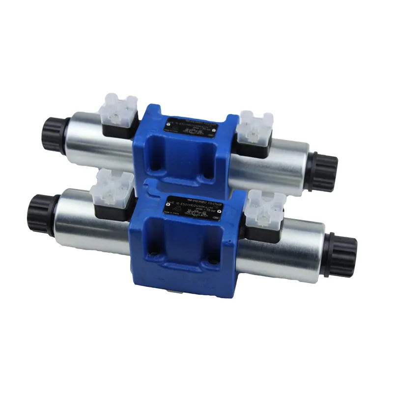
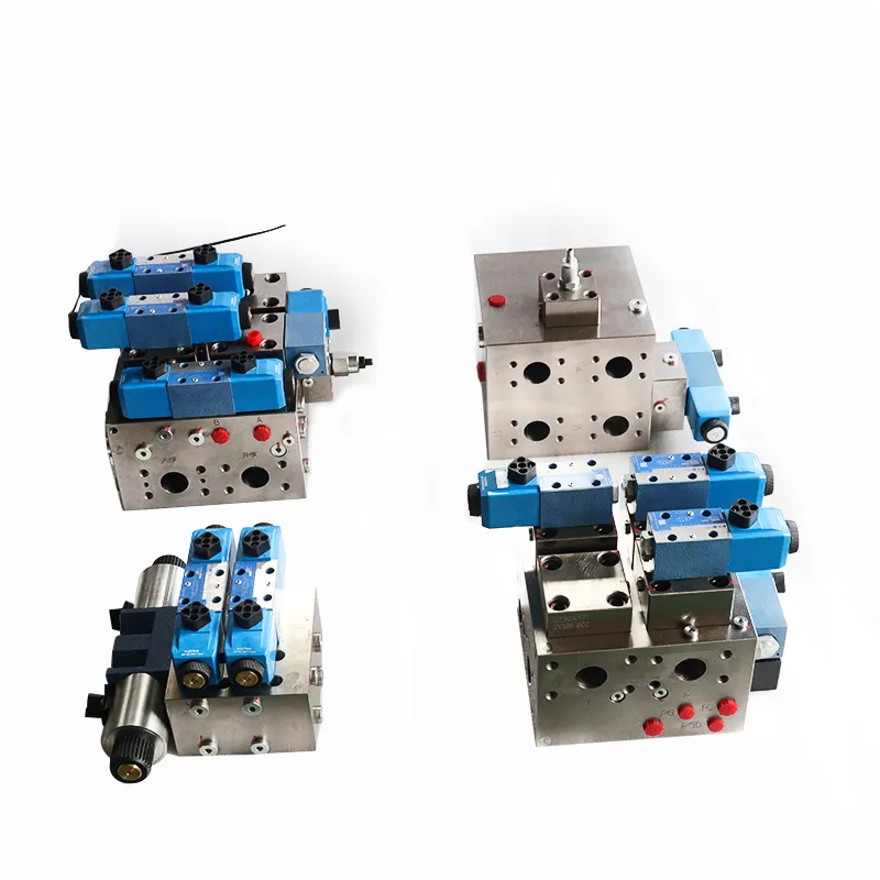
24v dc hydraulic solenoid valve is an industrial equipment controlled by electromagnetism, it is an automation basic element used to control the fluid, which belongs to the actuator.
The pneumatic solenoid valve is a type of valve that operates by controlling the movement of its valve body. We use this movement to block or allow the flow of oil through different discharge holes, while we keep the inlet hole open at all times. As a result, we direct hydraulic oil into various discharge pipes based on the valve’s configuration. Subsequently, the oil pressure within these pipes exerts force on the piston of a cylinder. We connect this cylinder to the pneumatic solenoid valve. Ultimately, we control the entire mechanical movement of the solenoid valve with the current flowing through the electromagnetic coil within the valve.
This article mainly introduces the pneumatic 24V DC hydraulic solenoid valve. It covers details about its positions and passes. Additionally, it explores solenoid valves, including their positions and passes. We discuss these aspects together to provide a comprehensive understanding.
24v dc hydraulic solenoid valve is how many position and how many way
Pneumatic 24v dc hydraulic solenoid valve according to the function and need, there are many pass, bit.
There are two two-way, two three-way, two five-way, two four-way, 24v dc hydraulic solenoid valve. (Two-position five-way, two-position four-way and divided into single electric control and double electric control two kinds).
There are three-position five-way; three-position five-way and: in the seal three-position five-way solenoid valve, medium pressure three-position five-way solenoid valve, in the drain three-position five-way solenoid valve, as well as three-position four-way solenoid valve. There are also special needs of four-position five-way solenoid valve (three solenoid head) and so on.
Of course, the simplest and most commonly used is the two-position three-way solenoid valve, two-position five-way solenoid valve.
If you need to stop the cylinder (actuator) in the middle of the 24v dc hydraulic solenoid valve.
Solenoid valve several positions and several passes detailed explanation (schematic)
Through’ and “position” is an important concept of pneumatic directional solenoid valve. Different ‘through’ and ‘position’ constitute different types of pneumatic directional solenoid valve.
Often referred to as ‘two-position valve’, ‘three-position valve’ refers to the spool of the directional valve has two or three different working positions.
The terms ‘two-way valve,’ ‘three-way valve,’ and ‘four-way valve’ refer to directional valves with valve bodies that have two, three, or four different ports. These ports can connect to different oil pipes or interfaces in the system. Different oil/gas paths can only pass between these specific ports. You can only connect the different oil/air lines to each other by switching the valve port when you shift the spool.
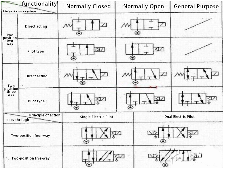
When dealing with the term “several” in relation to valves, it is important to consider how many working conditions the valve has. The number of working conditions can determine how many “several” refers to. For instance, in pneumatic component symbols, understanding this concept is crucial. The symbols used to represent the valve body, which often include a square (with arrows or T lines), indicate the number of channels or paths it has. Specifically, the number of these elements (arrows, T lines, etc.) within the symbol signifies the number of channels or paths the valve possesses. The back of the ‘several passes’, is on behalf of one of the square has a few points (and the arrow line and the T line intersection point), is a few passes.
The meaning of graphical symbols is generally as follows:
(1) the box indicates the working position of the valve, there are a few boxes means that there are a few ‘position’;
(2) The arrow in the box indicates that the oil circuit is on, but the direction of the arrow does not necessarily indicate the actual direction of the liquid flow;
(3) The symbol ‘┻’ or ‘┻’ in the box indicates that the circuit is not open;
(4) The number of ports connected outside the box is several, which means several ‘through’;
(5) In general, the valve and the system for oil or gas connected to the inlet / inlet with the letter p; valve and the system back to the oil / gas connected to the oil / return port with t (sometimes with o) that; and the valve and the actuator connected to the oil / gas port with a, b and so on. Sometimes in the graphic symbols used to indicate the leakage of oil port;
(6) Directional valves have two or more operating positions, with one being the normal position, which is the spool’s position when you do not apply a maneuvering force. The centre position in the graphic symbol is the normal position of a three-position valve. A two-position valve that uses a spring to reset the valve has its normal position as the path state in the box near the spring. When drawing a system diagram, you should generally connect the oil/air circuit to the normal position of the directional valve.
(The following diagram shows a three-position four-way)
The On-Off, five-way valve has five channels for air to pass through. One of these channels is connected to the air source. We connect two channels to the inlet and outlet of the external chamber of a double-acting cylinder, which in turn links to the inlet and outlet of the internal chamber. We connect the other two channels to the inlet and outlet of the internal chamber of a double-acting pneumatic actuator. You can reference the specific principle of operation of this valve from the principle of operation of a double-acting pneumatic actuator.
In the gas circuit (or similarly, in a liquid circuit), a two-position three-way solenoid valve serves a crucial function. It possesses three main holes, each serving a distinct purpose. The first is an inlet hole, which is designed to connect to the inlet air source. The second is an outlet hole, responsible for providing the target equipment with an air source. Lastly, there is an exhaust hole, typically equipped with a muffler to reduce noise. However, if noise is not a concern, the muffler can be omitted.
A two 5-way solenoid valve has multiple ports for air flow. It has 1 inlet hole, which is connected to the inlet air source. There is 1 positive action outlet hole, which provides a positive action air source to the target device. Additionally, there is 1 negative action air hole, which supplies negative action air to the target device. For exhaust, we include 1 positive action exhaust hole and 1 negative action exhaust hole, and we typically equip both with mufflers for noise reduction. For small automatic control equipment, we generally use 8–12mm industrial rubber air pipes.
Electrically, a two three-way solenoid valve generally has single electric control, meaning it uses a single coil. On the other hand, a two five-way solenoid valve generally has double electric control, meaning it uses two coils. Coil voltage level is generally used DC24V, AC220V and so on.
Two three-way solenoid valves are divided into two types: normally closed and normally open. The normally closed type refers to the valve where the gas path is broken when the coil is not energised. The normally open type refers to the valve where we keep the gas path open when we do not energize the coil.
The action principle of a two five-way double electric control solenoid valve involves energising the positive action coil. When we energize the positive action coil, we connect the positive action airway, specifically the positive action air outlet. Even if we de-energize the positive action coil afterwards, we keep the positive action airway connected. We will maintain this connection until we energize the reverse action coil. If we energize the reverse action coil, we turn on the reverse action air circuit. When we energize the reverse action coil, we supply air to the reverse action vent. Even if we de-energize the reverse action coil, the reverse action air circuit remains turned on. The reverse action air circuit will remain on until we energize the positive action coil.
This is equivalent to ‘self-locking’.The two-position five-way double electric control solenoid valve has specific characteristics. Based on these characteristics, you can design the electromechanical control circuit. Alternatively, you can also design PLC programming to actuate the solenoid valve coil. The actuation of the solenoid valve coil should be for 1 to 2 seconds. This approach helps protect the solenoid valve coil and reduces the risk of damage.
Contact Zhuo Yi Control Technology for the latest production technology!