
In hydraulic drive systems and proportional/servo control systems, you achieve the control of load motion by controlling the fluid flow. Assume that the fluid is incompressible at constant flow, and you can write its Bernoulli equation as follows:

Equation (2-3)
In the formula:
z — Distance of the centre of the overflow section from the horizontal datum (m).
p — pressure (Pa).
ρ — fluid density (kg/m^3).
g — acceleration of gravity, g = 9.81m/s^2.
v — average velocity on the overflow section (m/s).
Equation (2-3) is the Bernoulli equation for an ideal fluid, where the first term expresses the fluid potential energy, the second term expresses the fluid pressure energy, and the third term expresses the fluid kinetic energy. Due to the conservation of energy, the ideal fluid flows continuously through any two sections while maintaining constant total energy.

The subscripts in Eq. (2-4) indicate any two cross-section markers under the same flow bundle, respectively. Due to the specific application of hydraulic pressure, the actual fluid pressure in the MPa level, and the potential energy formed by the fluid level difference is very small (level difference of 10m caused by the potential energy equivalent to 0.1MPa), and therefore in the engineering is often ignored. Therefore, the equation can be expressed as a one-step formula (2-5), namely
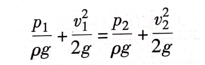
Equation (2-5) shows that during the flow of the same stream of fluid, the pressure decreases nonlinearly as the velocity increases and vice versa. Bernoulli’s equation explains why hydraulic valve components get stuck when the spool reverses. The flow path of the fluid when the spool reverses is the gap between the valve body and the spool. You can use the Bernoulli equation to calculate the value of the clamping force when the spool reverses.
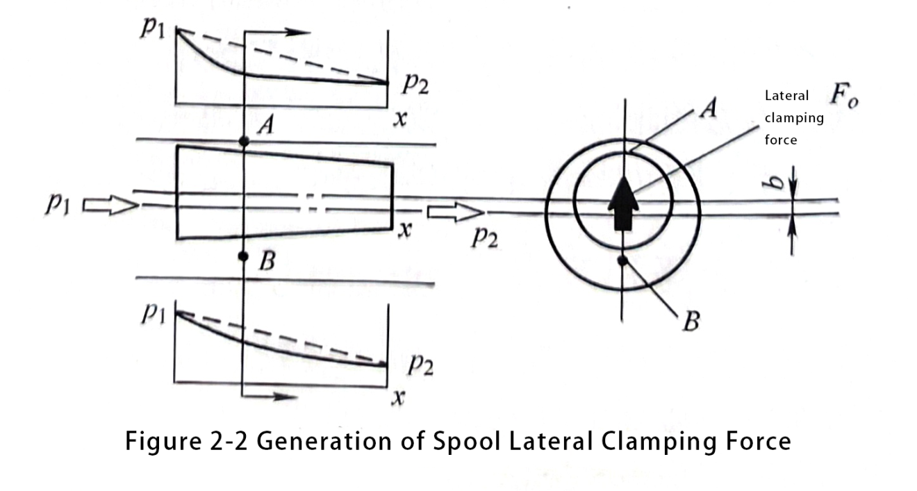
Figure 2-2, for example, if the anti-taper spool and the valve hole between the existence of eccentric distance b, the spool and the valve hole between the flow path will be offset, the lower flow path of the space B is greater than the upper flow path of the space A, according to Bernoulli’s equation can be known, the lower flow rate is slower than the upper part of the AB two fluid in the process of the pressure distribution curve as shown in Figure 2-2, therefore, in the spool of the lateral card tightness produced upward on the F0.
Lateral card tightness increases, will exacerbate the valve spool reversal card tightness value. Increased tightness will exacerbate the friction between the spool and the valve hole when the spool reverses. We call this friction hydraulic clamping force. Hydraulic clamping force in some cases is very considerable, for example, a diameter of 16cm long 12mm with the core, in the case of the working pressure of 21MPa, the diameter clearance 0.01mm, taper 0.004, if the friction factor to 0.15 counting, resulting in the clamping force can reach 158.9N.
One way to reduce or lower the hydraulic clamping force is to open an unloading groove on the spool. This method can effectively reduce the value of the lateral clamping force.
Another way is to use a smooth conical spool. This approach results in the opposite direction of the lateral clamping force, as shown in Figure 2-2. The clamping forces offset each other, ensuring that the spool remains aligned and avoiding the impact of hydraulic clamping force on the spool reversal.
Through the test also found that:
① spool clamping force in the fluid pressure of 14MPa when the maximum. At this time, use the method of unloading grooves. This approach can help reduce the difference in clearance between the spool and the valve hole. This, in turn, reduces the hydraulic clamping force.
② When the pressure rises to 32 MPa, the hydraulic clamping force will fall to zero. You can understand this as follows: high pressure increases the elastic deformation of the valve hole. As a result, the clearance between the spool and the valve hole changes.
Although theoretical analysis and explanation can guide fluid flow problems in hydraulic components, numerous factors influence specific products. Therefore, you can only obtain verification through testing. With the growing popularity of simulation technology, you can now use simulation methods for hydraulic component design. These methods address uncertain factors effectively. Previously, achieving results required a large number of tests, but now you can obtain these results at a lower cost. Additionally, you gain a clearer understanding of the influencing factors and the connections between the results. This leads to more ideal conclusions. This approach also significantly saves development time for the product. With the close combination of virtual simulation and physical components, hydraulic component design simulation technology will evolve. It will move towards a closed-loop digital twin technology direction. This direction will involve semi-physical simulation and digital data integration.
Contact Zhuo Yi Control Technology for the latest production technology!


