Hydraulic cylinder design should first master the original information and design basis, including: the use of the host and the work of the article out: the structural characteristics of the working mechanism, the load condition, stroke size and action requirements; hydraulic system selected by the working force and flow; materials, accessories and machining process of the reality of the situation; the relevant national standards and specifications and so on.
The internal structure and parts composition of the hydraulic cylinder are shown in Figure 26-112 and Figure 26-113.

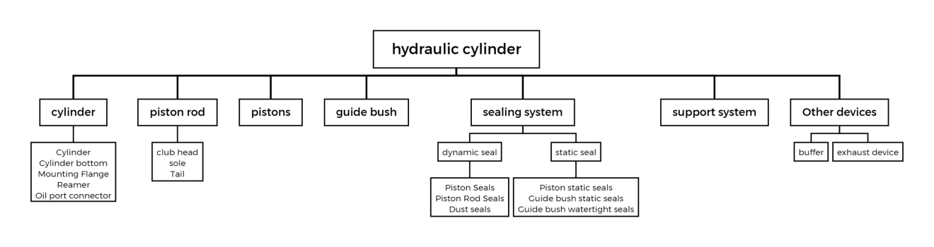
Compared to other hydraulic components, hydraulic engineers find the structural principles, calculations, and design of hydraulic cylinders relatively simple. Force and velocity calculations are performed in accordance with the formulas provided in Section 26.7.1. The main dimensions of a hydraulic cylinder include cylinder bore, piston cylinder diameter, cylinder length and cylinder wall thickness. However, you must pay attention to details to obtain a hydraulic cylinder with acceptable performance.
Hydraulic cylinder design according to the following principles: ① to meet the working conditions and installation requirements; ② to meet the force, stroke, speed requirements; ③ parts and components have sufficient strength, rigidity, to meet the requirements of service life and reliability; ④ sealing and reliable: ⑤ give full consideration to the parts processing and assembly technology; ⑥ installation, maintenance and convenience; ⑦ hydraulic cylinder cost-effective; ⑧ lightweight design; ⑨ standardised design.
The following points were noted in the design:
(1) Hydraulic cylinder type selection
The characteristics and needs of the load determine the type of hydraulic cylinder. Although people generally use double-acting cylinders more often, you can use a single-acting cylinder to reduce the oil pipe when self-weight, external loads, or spring force are present. This setup allows for borrowing the existing force. When it is necessary to achieve a long working stroke with a short installation length, consider using a multi-stage telescopic cylinder or adding a multiplier mechanism that can amplify the stroke. A thicker piston rod is required for a longer stroke. You may also equip the cylinder with a stop sleeve to improve the longitudinal bending resistance. For the structure of the cylinder barrel, general machinery and equipment typically use tie rod or threaded types. In contrast, the metallurgical industry, forging machinery, and other heavy-duty applications, as well as high-pressure large-diameter cylinders, often employ welded structures.
(2) Calculate and determine the basic structural parameters
Determine the change in the hydraulic cylinder’s load at various stages of the stroke based on the external forces it encounters. These forces include gravity, friction from external body movement, inertia, and the working load. Additionally, you must provide the power value for these conditions.
You determine the diameter of the piston and piston rod based on the working load of the hydraulic cylinder and the selected working pressure of the fluid. To do this, you follow the national standards.
You determine the flow rate of the hydraulic pump based on the speed of movement of the hydraulic cylinder and the diameter of the piston and piston rod.
Select the cylinder material and calculate the cylinder outer diameter.
Select the structural form of the cylinder head and calculate the strength of the connection between the head and cylinder barrel.
Selection of the stroke of the hydraulic cylinder depends on the load movement distance.
(3) hydraulic cylinder piston rod guide length (see Figure 26-114), stability and longitudinal bending strength
Hydraulic cylinder barrel length L is calculated as follows:
L=l+B+A+M+C (26-20)
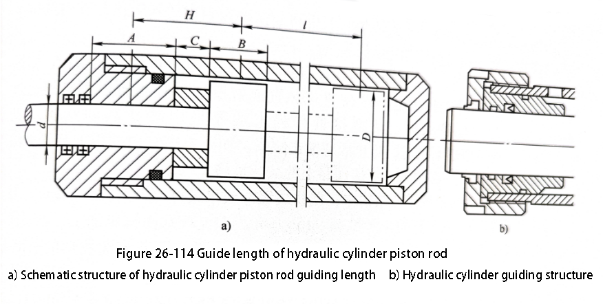
Where in the formula l – the maximum working stroke of the piston.
B–Piston length, generally (0.6~1)D(D<80mm) or (0.6~1.0)d(D>B-80mm);
A – piston rod guide length, take (0.6~1.5)D(D<80mm) or (0.6~1.5)d(D>80mm).
M–Piston rod sealing length, determined by the sealing method;
C – other lengths.
Suggested minimum guidance requirements H>l/20 or H=D/2. The length of the cylinder barrel should preferably be no more than 20 times the inner diameter.
The piston rod guide length A should not be too small, otherwise the initial deflection of the hydraulic cylinder (clearance-induced deflection) will increase, affecting the stability of the hydraulic cylinder. The length of the guiding sleeve generally varies depending on the size of the hydraulic cylinder and the type and use of the piston rod seal. It should be more than 0.6 times the diameter of the piston rod. This ensures that the piston rod has sufficient stability. See Figure 26-114 for reference.
The piston rod should have good stability, try to make the piston rod in the state of tension to withstand the maximum load.
The guide bush of high-speed and long-stroke hydraulic cylinder should adopt special structure. For hydraulic cylinders with speeds greater than 1000 mm/s and strokes of 4000 mm or more, localized overheating can occur due to high-speed action. This overheating can cause significant wear on the guide sleeve. Additionally, it may result in the appearance of metal powder. This requires that the guide sleeve surface receives forced lubrication. Additionally, we must apply high-frequency quenching and other special treatments to the piston rod surface. Additionally, we can consider using hydrostatic bearings.
When resistance acts on the piston rod, you must ensure that the rod diameter is large enough to withstand the load and the stresses exerted by the cylinder. At the same time large deflections must be avoided. When the strength of longitudinal bending is insufficient, friction of the sliding surfaces, etc. causes large deflecting loads on the guide sleeve and piston, resulting in problems such as jamming, creeping, and abnormal wear of seals. The additional strength required to prevent longitudinal bending depends on the stroke and pivot connection method.
Due to the slenderness of the piston rod, you should carry out a longitudinal bending strength check and a stability calculation of the hydraulic cylinder.
(4) hydraulic cylinder mounting method
The mounting method should be based on the load characteristics and the form of movement. The key is to ensure that the hydraulic cylinder is loaded along the direction of action. Additionally, the hydraulic cylinder should not experience a load in the radial direction.
Flange mounting provides high-strength centerline supports. Long cylinders may require additional supports at the free end to prevent sagging. Additionally, take care to mount bolts in a way that avoids shear forces.
(5) hydraulic cylinder with internal buffer braking device and the new buffer device
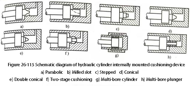
High-speed actions with a heavy load can sometimes damage mechanical devices or hydraulic cylinders due to the impact pressure generated in the buffer section. When the cylinder speed exceeds 200 m/s, and the mass in motion is large, you should use a braking structure (see Figure 26-115). This braking structure should be placed near the end of the piston stroke. This structure gradually decelerates the piston to prevent it from impacting the cylinder head. If the buffer device in the cylinder alone can not absorb all the inertial energy, must also consider the hydraulic circuit deceleration measures.
Figure 26-115 shows a variety of cushioning structure, parabolic cushioning effect is the best (see Figure 26-115a), but the need for CNC machine tool processing, the cost is higher, while Figure 26-115b shown in the shape of the throttle groove by the milling machine processing, convenient and simple, more applications. The stepped buffer (see Figure 26-115c) typically produces a pressure peak. This pressure peak is less than half that of the constant throttle cylindrical buffer.
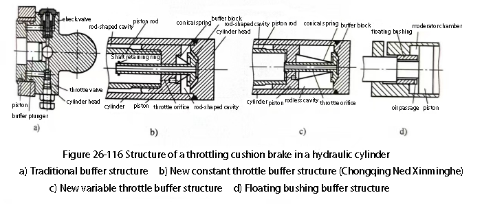
Due to this characteristic, the stepped buffer is frequently used in the rodless cavity of hydraulic cylinders. The double conical buffer (see Figure 26-115e) performs better than the conical buffer (see Figure 26-115d) and engineers often apply it in excavator hydraulic cylinders. The porous cylinder and porous plunger buffers (see Figure 26-115f、h) can achieve a buffering effect that closely approximates the ideal parabolic level. Figure 26-116a shows the specific structure of the buffer for hydraulic cylinders. The traditional hydraulic cylinder buffer structure is very common.
The new variable throttling cushioning structure currently has a variety of, including constant throttling or variable throttling cushioning structure (see Figure 26-116b, c and floating bushing self-regulating flow type cushioning structure (see Figure 26-116d) and so on.
In the constant throttle cushioning structure shown in Figure 26-116b, the piston moves towards the cylinder head. Under the action of the retaining ring and conical spring, the cushioning block also moves with the piston towards the cylinder head. When the buffer block is compounded with the cylinder head plane, a buffer oil chamber is formed in the rodless cavity. The throttle hole discharges the enclosed oil, thereby achieving a constant throttle buffer. The variable throttle buffer structure shown in Figure 26-116c improves upon the constant throttle buffer structure. It does this by incorporating small holes in the oil inlet pipe of the buffer block. This design allows the throttling area to change as the piston moves toward the cylinder head. It achieves variable throttling by altering the number of throttling holes.
The new throttle-type buffer device features conical springs and a constant (variable) throttle buffer structure. Compared to cylindrical springs, conical springs provide greater lateral stability. The vibration frequency is a variable value, which prevents resonance phenomena. This design avoids pressure pulses and excessive buffer chamber pressure peaks. It ensures that the pressure changes gradually. This structure saves the lateral size of the traditional buffer plunger. It also reduces the buffer stroke. The structure is simple and low cost. At the same time, the hydraulic cylinder’s reverse movement in and out of the oil occurs normally.
(6) the exhaust problem of the hydraulic cylinder
Air intrusion into the cylinder often results in the hydraulic cylinder shaking or crawling during movement. To resolve this, add an exhaust device or move the hydraulic cylinder rapidly to its maximum stroke to forcefully expel the air. However, gas in the hydraulic cylinder is not the only cause of the crawling phenomenon. Installing the hydraulic cylinder with a non-parallel guide rail can also cause crawling. This happens because the non-parallel guide rail results in large resistance. In this case, adjust or re-install the cylinder.
(7) Oil port flow rate
The oil port flow rate should not exceed 7m/s to avoid excessive pressure loss affecting the cylinder output.
(3) Selection of sealing materials
Sealing to consider the compatibility of the material with the oil, applicable temperature, speed range and dustproof and other devices.
Contact Zhuo Yi Control Technology for the latest production technology!