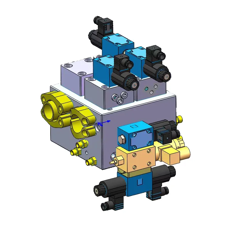
The servomotor pump is a new hydraulic variable speed control product that has recently appeared. It consists of a servomotor (either AC or DC) and a hydraulic quantitative or variable pump. Servomotor pumps constitute the power source of the hydraulic system provides the use of electric motor speed regulation method to carry out the hydraulic system flow regulation, due to the regulation process instead of hydraulic pump variable control valves (pump-controlled pressure valves, load-sensitive valves, power regulating valves, proportional valves, or switching digital valves, etc.), or instead of hydraulic control valves to regulate the speed of the hydraulic system to reduce the pressure loss, so that the flow of the regulation of the process of energy saving.
The servo motor is suitable for both forward and reverse rotation and provides smooth operation. Its response time can meet the requirements for some industrial applications, such as in the plastic machinery industry. As a result, the combination of a servo motor, drive, and internal gear pump has led to the development of high-end speed control technology application products. This equipment is applicable to various types of machinery. It includes plastic machinery, die-casting machinery, and shoe leather machinery. Additionally, it is suitable for textile machinery, hydraulic presses, and hydraulic engineering machinery. It is especially suited for high-energy-consuming machinery that urgently requires energy-saving transformation. In this regard, Japan, Germany’s products are more mature, has produced a considerable brand effect in the market.
The structure of a cup rotor AC servomotor consists of four parts: the outer stator, the cup rotor, the inner stator, and the pulse counter. Figure 2-9 shows only the rotor part, which is different from a unidirectional induction motor.

The most obvious difference between the two is that they have a control winding in the servomotor winding. The manufacturer makes the rotor from a non-magnetic conducting material (e.g., copper), while the inner stator functions as the magnetic circuit. The excitation winding is controlled by the control voltage U of the control winding. When you apply the control voltage \( U \) to the excitation winding, it creates a two-phase rotating magnetic field in series with the capacitor. By selecting the capacitance appropriately, you can make the current phase difference between the two windings close to 90°. This rotating magnetic field can then be regarded as the synthesis of two circular rotating magnetic fields. However, these two circular rotating magnetic field speed is the same, opposite direction, but the amplitude is not equal.
At this time, they cut the potential and current induced by the rotor winding. The electromagnetic torque they generate points in the opposite direction and varies in size (the forward rotor experiences a larger torque, while the reverse rotor experiences a smaller torque). As a result, the synthetic torque is not zero, causing the servo motor to rotate towards the direction of the forward magnetic field. With the enhancement of the control winding signal \( U \), the magnetic field approaches a circular field. Consequently, the forward magnetic field and its torque increase, while the reversed magnetic field and its torque decrease. This increase in synthetic torque leads to a rise in the rotor speed, assuming the load torque remains constant.
If the phase of \( U \) changes, such as by shifting it 180° (polarity change), the rotating magnetic field will turn in the opposite direction. Consequently, the synthetic torque generated will also reverse direction.As a result, the servomotor will reverse its direction of rotation. If the control signal disappears and only the excitation winding is energized with current, the servo motor will generate a pulsating magnetic field. This occurs because the magnetic field produced lacks the control signal. The synthetic torque \( T \) produced by the positive and negative rotating magnetic fields, which is divided into the pulsating magnetic field, will point in the direction opposite to the rotating direction. Consequently, the motor will stop immediately when you control the control winding voltage to be zero. This is the mechanism of servomotor speed control.
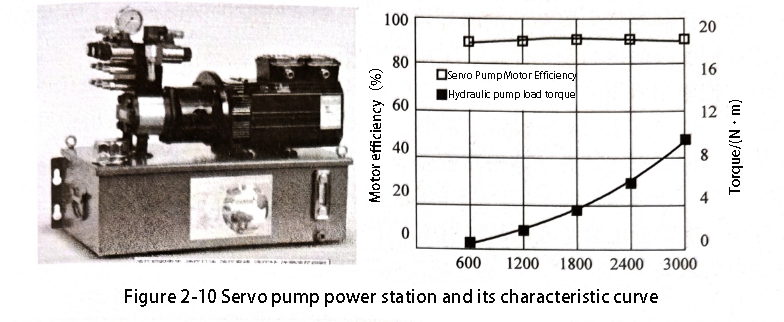
Developers are advancing servo motors towards integrated designs, including brushless DC motors and permanent magnet synchronous motor systems. These integrated motors are becoming the mainstream in speed regulation and servo applications. Additionally, Figure 2-10 shows the characteristic curves of servo pump power stations. And pulse width modulation (PWM) technology is the basis of motor control digitalisation.
An electro-hydraulic servo energy-saving system can include several key components. It consists of an electro-hydraulic servo drive and a three-phase AC permanent magnet synchronous motor. Additionally, the system features a high-performance professional servo pump and a pressure sensor, along with other components. By adopting vector control, weak magnetic control, and a special PID control algorithm, the system can achieve precise regulation. These techniques enable the system to accurately control the pressure and flow required throughout the entire working process. This approach eliminates the energy loss associated with high-pressure throttling.
As a result, it achieves energy and power savings while also reducing the temperature of the system oil. The highest efficiency reaches 65%, and the average efficiency is more than 30%. Table 2-19 lists the performance comparison between servo pumps and piston variable pumps. As this table shows, the servo pump offers slightly higher pressure and flow responses compared to the plunger type variable pump. Additionally, it controls noise effectively, saves energy well, has high repeatability, and improves low-speed low-pressure characteristics.
Table 2-19 Comparison of Servo Pump and Piston Variable Pump Performance
| servo pump | piston variable pumps | ||
| Flow Rate Characteristics | linearity | 1% | 2% |
| hysteresis | 1% | 3% | |
| Maximum Flow Response/ms | 85 | 120 | |
| Repeatability | 1% | 2% | |
| Pressure Characteristics | Maximum rated pressure/MPa | 20 | 25 |
| linearity | 1% | 3% | |
| hysteresis | 1% | 2% | |
| Maximum pressure response/ms | 85 | 120 | |
| Repeatability | 1% | 2% | |
| Noise/dB | 68 | 78 | |
| flow rate | small | large | |
| Power savings (vs. dosing pump systems) | More than 40% | More than 20% | |
| Low-speed low-pressure controllability | good | general | |
| Requirements for hydraulic fluids | MAS 11 | NAS 9 | |
Contact Zhuo Yi Control Technology for the latest production technology!
You can contact us by email or WhatsApp.