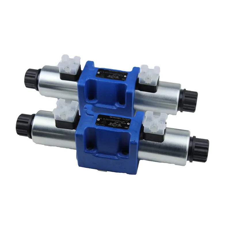
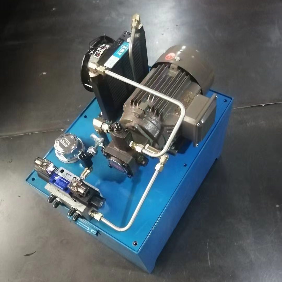
2 position hydraulic solenoid valve in automation projects are quite widely used, 2 position hydraulic solenoid valve are divided into pneumatic valves and hydraulic valves, their structure and usage are the same, pneumatic valves in non-standard automation and other out of the smaller industrial environments are more applications, hydraulic valves in CNC CNC is used more, the use of which are also very simple, and can be said to be the beginner’s introduction to the automation of the first thing to learn.
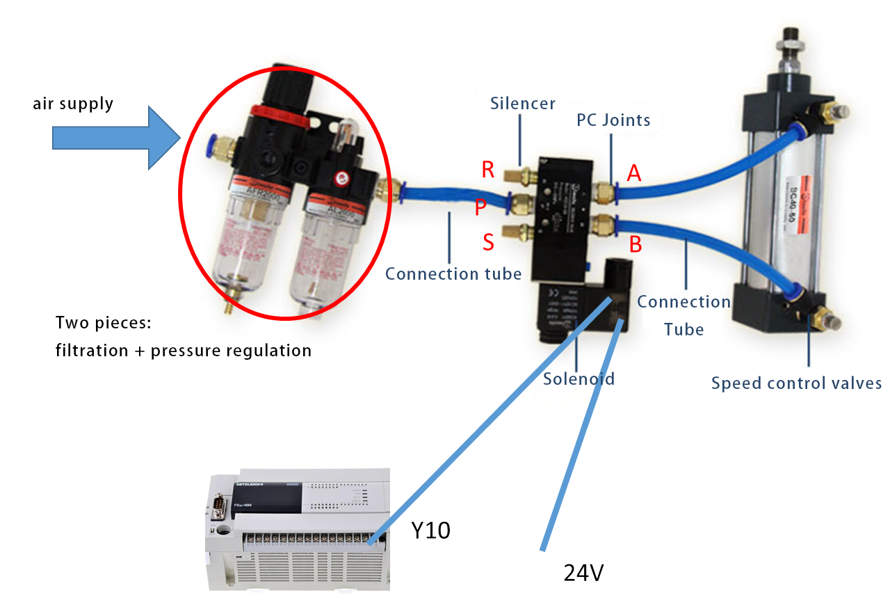
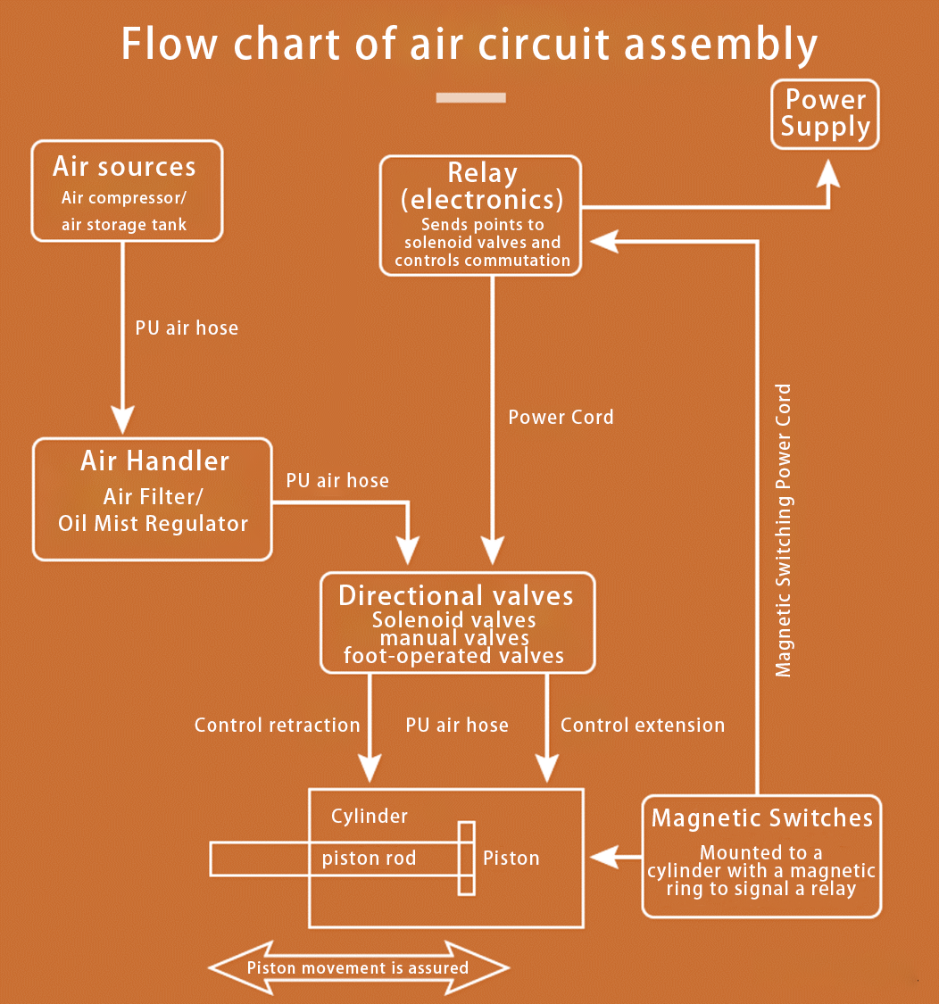
A simple air circuit diagram is shown below:
Structure of solenoid valves
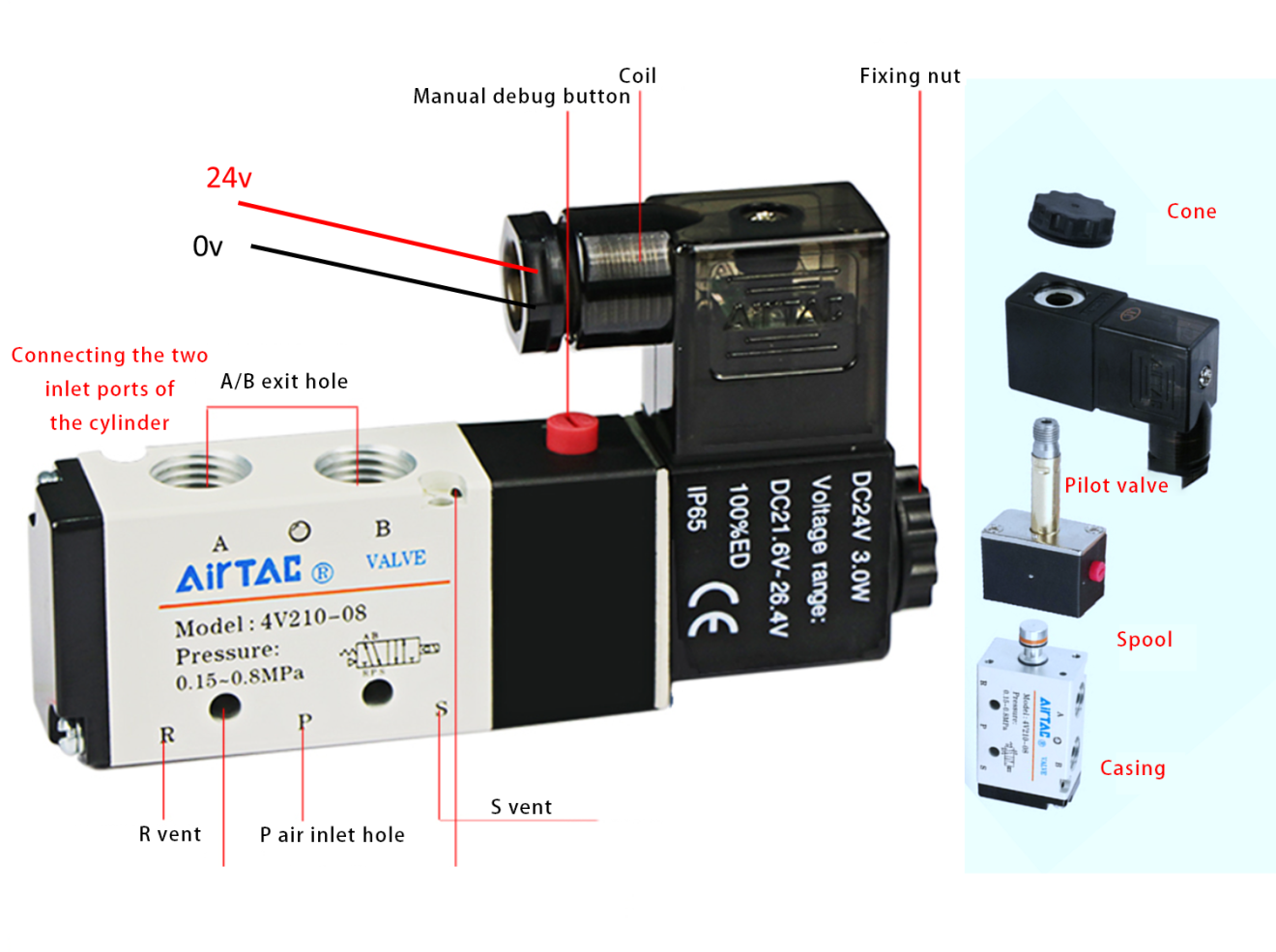
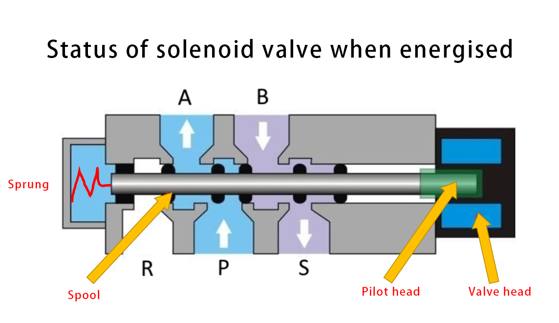
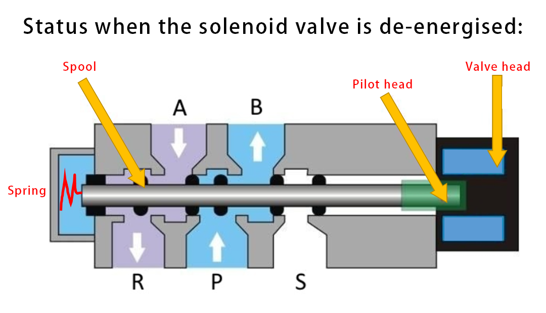
Solenoid valve consists of head coil, pilot head, spool and mechanical body, the head is mainly used to generate electromagnetic force, the pilot valve moves under the action of electromagnetic force, the spool is displaced under the action of the pilot valve to achieve the switching of gas flow.
As shown in the figure below:
Working Principle of Solenoid Valve
The solenoid valve is mainly composed of electrical and mechanical parts, through the valve head energised to achieve a change in the direction of the gas flow, thus driving the extension and retraction action of the cylinder.
The status of the solenoid valve when it is energised is shown below:
The status of the solenoid valve when it is de-energised is shown below:
Assembly of solenoid valves in the gas circuit
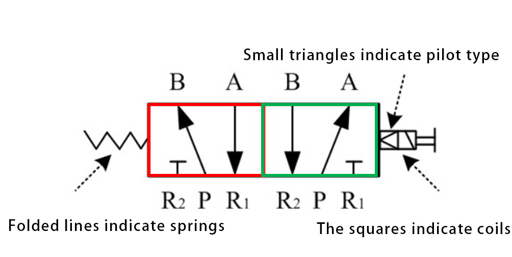
Explanation of gas path symbols in solenoid valves
The red box on the left indicates the state when the solenoid valve is de-energised, and the arrow indicates the direction of gas flow; the green box on the right indicates the state of gas flow when the solenoid valve is energised.
P:gas inlet
R:Exhaust port
S:Exhaust port
A:Cylinder inlet port 1
B:Cylinder inlet 2
The picture below has 2 boxes, representing 2 positions, with 5 holes, so it’s called a five-way, or two-position five-way;
Solenoid valve wiring in use
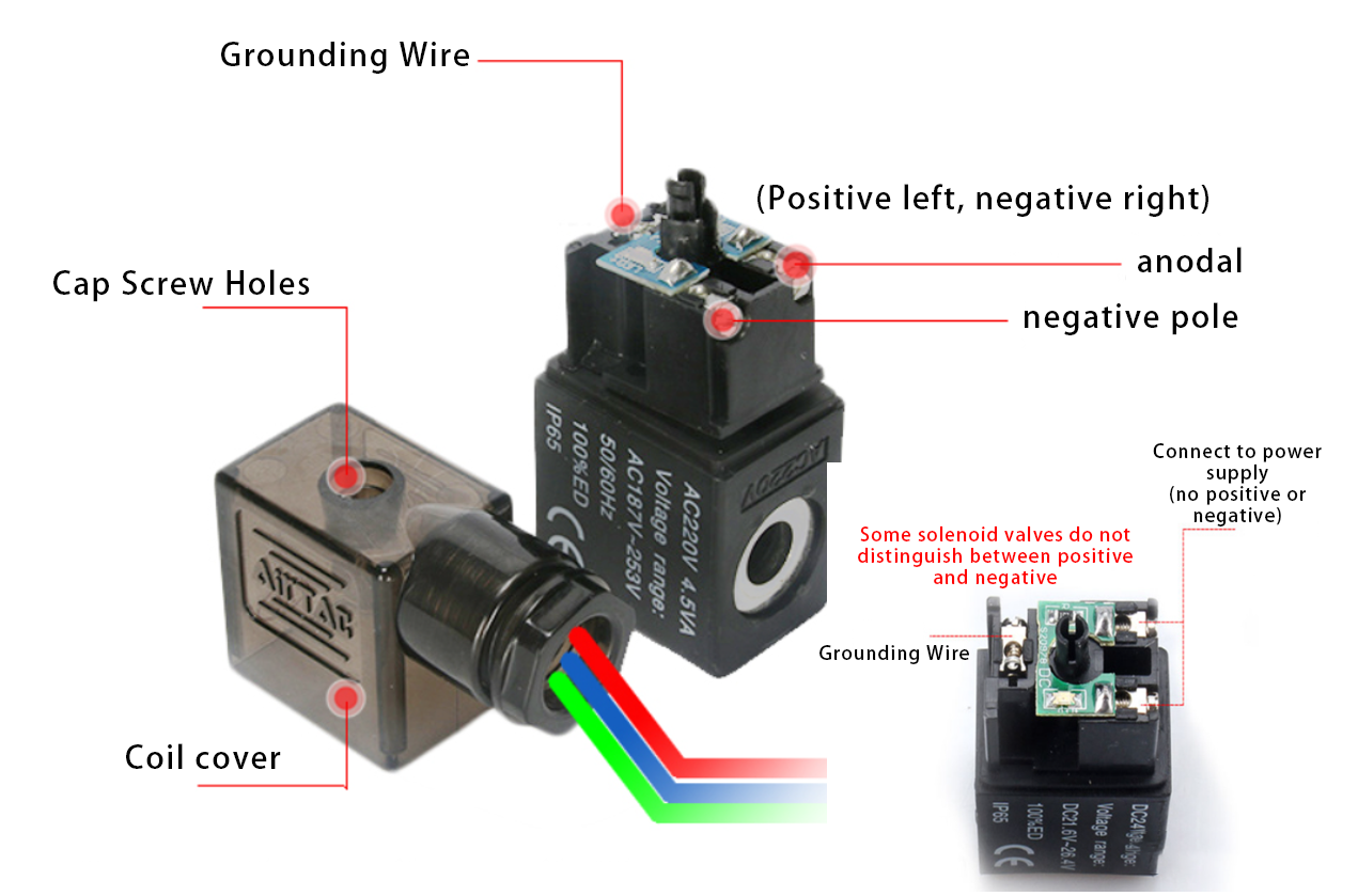
Valve head power supply 12V, 24V, 220V, power naturally large and small, completely according to the equipment’s own needs to choose, usually gas valve power 2W, voltage 24V, hydraulic solenoid valve power 30W; wiring diagram as shown below, while paying attention to the positive and negative poles of the next power supply wiring, connecting the reverse will lead to the valve does not work.
Contact Zhuo Yi Control Technology for the latest production technology!