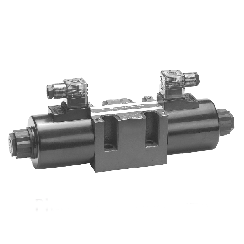
Solenoid valve for hydraulic is a device that uses electromagnetic force to control the flow of fluid or gas. It is mainly composed of valve body, spool, electromagnetic coil and spring.
When the solenoid coil energizes, it generates a magnetic field that attracts or repels the spool. This action controls the flow direction and speed of the medium.
We widely use solenoid valve for hydraulic in automation control systems, industrial production, petrochemical, and other fields. They offer advantages such as a simple structure, fast response speed, and high reliability.
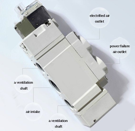
Pneumatic solenoid valves have many passes and positions according to function and need.
There are two two-way, two three-way, two five-way, two four-way, solenoid valve.(Two-position five-way, two-position four-way and divided into single electric control and double electric control two kinds).
Of course, the simplest and most commonly used is the two three-way solenoid valve, two five-way solenoid valve. If you need to stop the cylinder (actuator) in the middle of the three-position five-way solenoid valve.
In pneumatically operated directional solenoid valves, we consider “through” and “position” as important concepts.
Different “passes” and “positions” make up the different types of pneumatically operated directional solenoid valves.
Often referred to as “two-position valve” “three-position valve” refers to the spool of the directional valve has two or three different working positions.
The terms “two-way valve,” “three-way valve,” and “four-way valve” refer to directional valves with two, three, or four different valve body configurations that can connect to different oil or gas pipelines in the system. The spool valve port switch shifts to communicate between different oil or gas pipelines. The number of working conditions of the valve corresponds to the number of configurations. For example, in pneumatic component symbols, it is easier to understand the valve’s configuration by looking at the number of squares (with arrows or T lines) in the symbols.
The back of the “several passes”, is on behalf of a square in which there are several points (and the arrow line and the T line intersection of the points) is several passes.
The meaning of graphical symbols is generally as follows
(1)The box indicates the working position of the valve, and several boxes indicate several “positions”;
(2) The arrow in the box indicates that the oil circuit is in the on state, but the direction of the arrow does not necessarily indicate the actual direction of the liquid flow;
(3) box symbol “on” or “a” that the access is not;
(4) The number of interfaces connected to the outside of the box there are several, that a few “through”;
(5) In general, the valve and the system supply oil or gas connected to the inlet / inlet with the letter p; valve and the system back to the oil 1 gas;
Road connected to the return oil / return port with t (sometimes with o) said; and the valve and the actuator connected to the oil port / gas port with a, b, etc. said. Sometimes used in the graphic symbols to indicate the leakage of oil port;
(6) directional valves have two or more working positions, one of which is the normal position, i.e.,the manipulation force does not affect the position of the spool.
The centre position in the graphic symbol is the normal position of a three-position valve. A two-position valve that uses a poppet reset has its normal position as the state of the path in the box near the spring.
When we draw a system diagram, we should generally connect the oil and gas lines to the normal position of the directional valve.
How many bits, refers to the valve has several operating states, how many operating states is how many bits. Corresponding to the graphical symbol of the square has a few is a few bits.
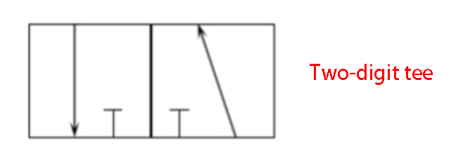
Several passes, meaning that one of the squares has several points. Corresponding graphical symbols are the arrow line and T. The arrow line has two points at each end, and the T represents one point.
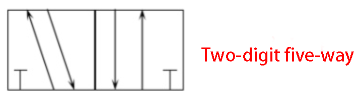
The arrow points to the direction of gas flow in the gas circuit, and the two-way arrow indicates that the gas can flow in both directions.
T indicates that the path is not accessible.
Two-position three-way (1 inlet, 1 outlet, 1 exhaust)
2-position 5-way (1 inlet, 2 outlets, 2 exhausts)
We generally indicate the air inlet with “P,” the exhaust with “R” and “S” (on the same side as the air inlet), and we use “A” and “B” to indicate the air ports connected to the actuator. We indicate the air ports connected to the actuator with “A” and “B”
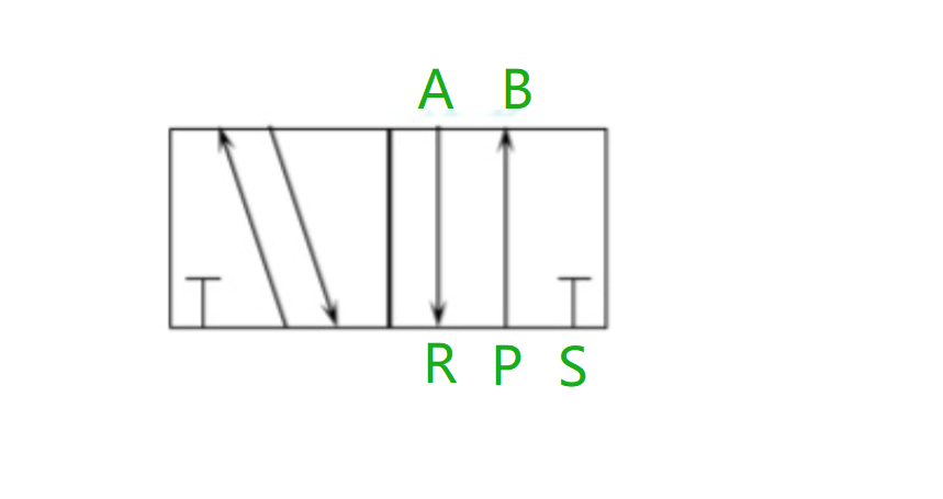
Generally, solenoid valve for hydraulic have two or more operating positions. One of them is the normal position.
The normal position refers to the position of the spool when electromagnetic force does not act on it (as shown in the figure, where the box is near the spring end).
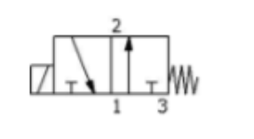
So:
NC below is a normally closed solenoid valve Q (when not energised, the gas is off)
The following figure NO is a normally open solenoid valve Q (when not energised, the gas is on).
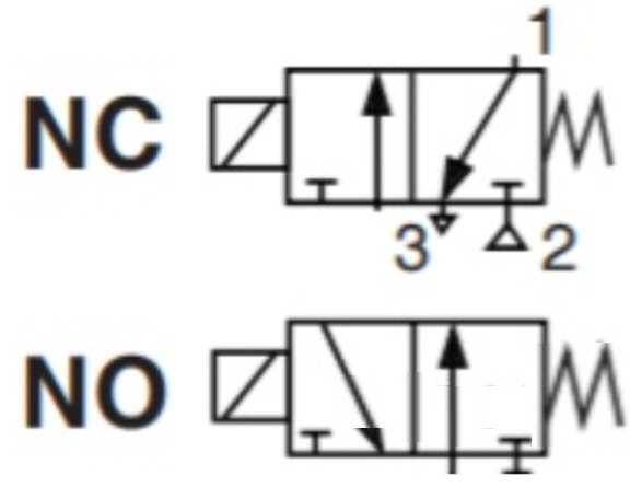
- When the solenoid valve for hydraulic needs to operate for a long time and the continuous opening time is much longer than the closing time, we should use a normally open solenoid valve.
- When the solenoid valve for hydraulic frequently switches between open and close positions, or when the open and close times are almost the same, we select a normally closed solenoid valve.
———————————————————————————
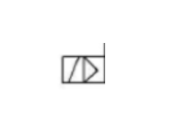
The symbols below indicate that the solenoid valves are direct-acting

The symbols below indicate that the solenoid valves are pilot operated
———————————————————————————
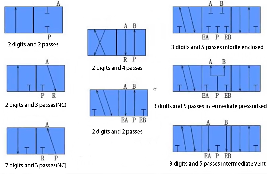
The bottom line is ventilation with five channels
- 1 of them is connected to the gas source
- We connect two ports to the inlet and outlet of the external air chamber of the double-acting cylinder
- Two are connected to the inlet and outlet ports of the internal air chamber.
You can refer to the working principle of the double-acting pneumatic actuator for the specific working principle, particularly regarding the air (or liquid) circuit:
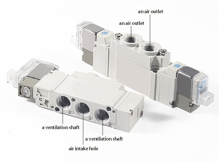
- A two three-way solenoid valve has 1 inlet hole (which we connect to the inlet air source), 1 outlet hole (which supplies air to the target device), and 1 exhaust hole (where we generally install a muffler, though we can choose not to install one if noise is not a concern).
- The two-position five-way solenoid valve has one inlet hole, which we connect to the inlet air source. It also has one positive-action outlet hole and one negative-action outlet hole. These holes provide air to the target equipment’s positive and negative actions. Additionally, the valve features one positive-action exhaust hole and one negative-action exhaust hole, where we can install mufflers.
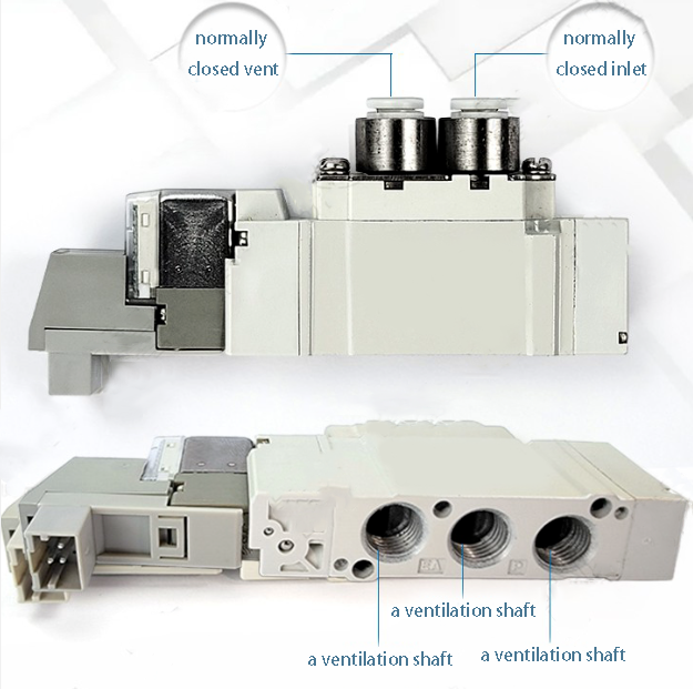
For small automatic control equipment, we generally use 8 to 12 industrial rubber gas pipes.
Electrically, the two three-way solenoid valve generally uses a single electric control, meaning it has a single coil. In contrast, the two five-way solenoid valve generally uses a double electric control, meaning it has two coils.
Coil voltage level is generally used DC24V, AC220V and so on.
We divide the two-position three-way solenoid valve into normally closed type and normally open type.
- In the normally closed type, the air path closes when we do not energize the coil.
- Normally open type means that the coil is not energised when the air path is open.
Two-position five-way double electric control solenoid valve action principle:
- When we energize the positive action coil, it connects the positive action air circuit (air flows through the positive action air outlet hole). Even if we de-energize the positive action coil, the positive action air circuit remains on. It will stay on until we energize the negative action coil.
- When we energize the reverse action coil, it turns on the reverse action air circuit (supplying air to the reverse action air hole). Even if we de-energize the reverse action coil, the reverse action air circuit remains on. It will stay on until we energize the positive action coil. This is equivalent to “self-locking”.
Based on this characteristic of the two-position five-way double electronically controlled solenoid valve, you can design the electromechanical control circuit. Alternatively, you can prepare the PLC program accordingly.You should let the solenoid valve coil activate for 1 to 2 seconds. This action helps protect the solenoid valve coil from damage.
Contact Zhuo Yi Control Technology for the latest production technology!