Introduction
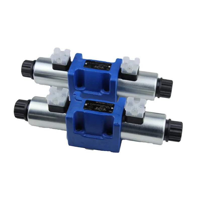
The importance of hydraulic control block in the hydraulic system has been more and more people know, and its application range is more and more extensive.The use of a hydraulic valve block can simplify the design and installation of the hydraulic system. It also facilitates the integration and standardization of the hydraulic system. This approach helps reduce manufacturing costs and improves both precision and reliability.
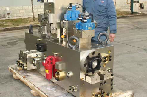
With the increase in the complexity of the hydraulic system, the requirements for the hydraulic control block are also becoming more stringent. This increases the difficulty of manufacturing and processing inspection for the hydraulic control block. If we do not plan the processing process carefully, we will face several issues. These issues include increased processing costs, wasted raw materials, and lower production efficiency.
This paper focuses on a typical hydraulic control block for in-depth study. We will explore the machining process, jigs and fixtures, tool selection, and other aspects to find and address various issues. Our goal is to solve problems such as low production efficiency, high costs, and unstable dimensional accuracy in the production of hydraulic control blocks.
Hydraulic control block Overview
The role of hydraulic control block
A hydraulic valve is an automation element operated by pressure oil. The pressure oil of the pressure distribution valve controls it. Typically used in combination with an electromagnetic pressure distribution valve, it can remotely control the on and off of oil, gas, and water pipeline systems in hydroelectric power stations. The core component of the hydraulic valve is the hydraulic control block, the hydraulic control block plays an important role in the hydraulic valve to control the direction of liquid flow, pressure and flow.
Machining precision
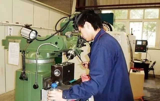
The surface roughness of the mounting valves and flanges on the hydraulic valve block should reach Ra0.4, and the surface roughness of the sealing surfaces of the end fittings should reach Ra3.2. In addition, the perpendicularity tolerance between the screw holes of the mounting fittings and their outer fitting surfaces should be at least grade 8.
We should set machining accuracy requirements for all screw holes on the valve block, generally choosing 7H. We should attach the machining accuracy requirements for threaded cartridge valve mounting holes to the product samples. We should maintain a roughness of Ra0.8 for cartridge valve mounting holes, in addition to meeting size tolerance and shape tolerance requirements. 0-ring groove surface roughness Ra3.2, the surface roughness of the general flow path Ra12.5.
Material Selection
We should make high-pressure valve blocks from 35 forged steel and use A3 steel or ductile cast iron for general valve blocks. When we cut the valve block material from the plate using gas cutting, we should leave sufficient machining allowance. It is better to forge the blanks of the valve blocks before machining. Processing of the valve block material to ensure that the internal organisation of dense, there shall be no interlayers, trachoma and other defects, if necessary, the blank should be flaw detection. Cast iron blocks and larger steel blocks should be aging treatment and pretreatment before processing. The workpiece material in this paper is QT400-18.
Hydraulic control block machining difficulties analysis
Difficulty 1、 low processing efficiency
First of all, the clamping process is quite cumbersome. The focus is on the processing method for the intersecting holes in the B-B sectional view (see below). Normally, processing requires clamping three sides of the workpiece. This involves performing three separate clamping operations. Additionally, the Φ4 diagonal holes require a fourth clamping operation.Ensuring accurate alignment of the holes with each other is challenging.
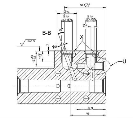
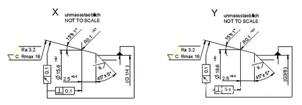
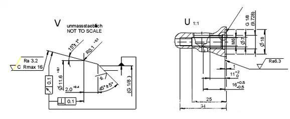
Secondly, the machining process requires a variety of tools. For example, as shown in the X, Y, V, and U partial views (see below), the holes are quite complex. In the X view, the 45°, 15°, and R0.1 features require three specialized tools for machining. Additionally, meeting the roughness, shape, and position tolerance requirements as specified in the drawings is challenging. These factors affect the overall machining efficiency.
Difficulty 2、 high form and position tolerance
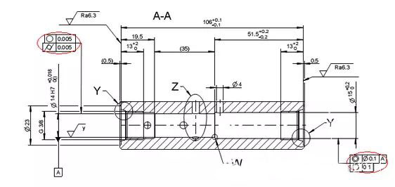
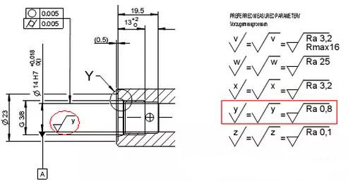
The drawing shows that we need to ensure the roundness and cylindricity of the center hole are within 0.005mm, and the coaxiality of the Φ14 and Φ15 holes is within 0.1mm. Ensuring that we meet these requirements is crucial for determining whether the entire part will be qualified after processing.
Difficulty 3、high roughness requirements
The figure below shows that we must ensure the roughness of the center Φ14H7 hole is below Ra0.8 while meeting the strict behavioral tolerance requirements. This increases the machining difficulty of the center hole and raises more demanding requirements for the technician’s process arrangement and tool selection.
Difficult solutions
Design of Workwear
After carefully analyzing the drawings, we decided to machine the intersecting holes in the B-B sectional view on a vertical machining center with a rotary axis. This approach reduces the number of workpiece clamping times and also addresses the issue of the angle of the Φ4 diagonal holes.
The design of the workpiece is shown in the figure below. The workpiece is positioned by three pins on one side, following the principle of six-point positioning. On one side of the workpiece, three degrees of freedom are constrained. Two long pins limit two degrees of freedom, while one short pin limits one degree of freedom. The workpiece is clamped in two parts at a time. The first part is the hole for the fastening screw.
Figure ① is the workpiece fastening screw holes, through the four holes shown in drawing C-C section of the workpiece will be fastened to the workpiece on top of the tooling;
Figure ② for the positioning pins, of which the middle two for the long pin (exposed length of about 15mm), the left and right sides of the short pin (exposed length of less than 3mm), in order to prevent in the process of machining and tool interference problems;
Figure ③ for the fastening screw holes, through the sub-hole will be fastened to the workpiece and the machining centre rotary disc. We should note that we have carefully processed the four corners of the workpiece. We created four arcs that align with the centripetal arc of the workpiece’s rotary center. This design helps solve the problem of repeated positioning each time we clamp the workpiece. Each time we clamp the workpiece, we use a percentage meter to check the runout of the four arcs; if it is less than 0.02mm, it meets the requirement.
Composite tool selection
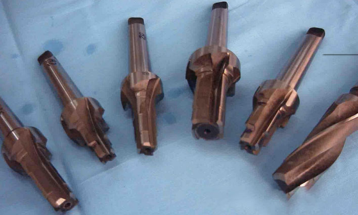
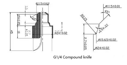
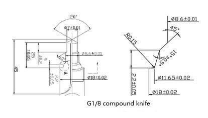
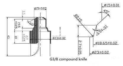
A composite tool is a specialized tool that combines two or more hole machining tools, whether of the same or different types, into a single unit. It can perform drilling, reaming, countersinking, and boring holes in a single machining process. This type of tool can also handle other multi-process operations with different process combinations. Composite tools are known for their high efficiency, accuracy, and reliability in both forming and machining. To reduce the number of tools required for machining the X, Y, V, and U partial views, we choose the composite tool. By customizing the carbide composite tool, we further decrease the number of tools needed. One tool can simultaneously process the threaded bottom hole, 45°, 15°, R0.1 chamfer, and outer countersinking holes. This approach significantly improves machining efficiency.
The composite tool design is as follows:
Process solutions for centre spool holes
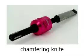
In order to achieve the drawing requirements, H7 tolerance level, roundness 0.005mm, cylindricity 0.005mm, roughness Ra0.8, two holes coaxiality 0.1mm, we use the drilling, boring, reaming, rolling processing technology, firstly through the alloy drill to the bottom hole Φ13 go to the processing amount; secondly with Φ13.8 and Φ15.1 rough boring tool two-way boring to ensure the position of the hole Secondly, Φ13.8 and Φ15.1 rough boring tools are used to bore the hole in both directions to ensure the positional accuracy of the hole; secondly, Φ13.99 alloy reamer is used to stabilise the diameter of the hole (generally, the diameter of the hole after reaming is Φ14+0.002 -0.002, and the roughness is Ra1.6); and lastly, the micro-adjustable rolling tool is used to ensure the dimensional accuracy of the hole, and at the same time to achieve the roughness value required in the drawing.
Process improvement results
After improving the process, we tested the processed workpieces and found that all were qualified. This includes the spool hole size of Φ14.013mm, with roundness and cylindricity measuring 0.002mm and 0.004mm respectively after three-coordinate measurement. We measured the roughness with a roughness meter at Ra0.3. We reduced the processing time from the original 90 minutes (machining center time) to 20 minutes, significantly improving the dimensional stability. After the process improvement, we saw a 10% increase in tool costs. However, machining time decreased by 45%. Additionally, the product scrap rate improved significantly, dropping from the original 5% to the current 0.5%. Although the tool cost is slightly higher, the overall machining cost has decreased by 50% compared to the original cost.
Concluding remarks
The use of hydraulic control blocks has led to a qualitative leap in the integration of hydraulic systems. This advancement not only simplifies system installation but also increases the reliability of system operation. Currently, domestic hydraulic manufacturers have designed and manufactured hydraulic valve blocks for various hydraulic systems. Over time, they have gradually developed standardized and stereotyped products. Traditional processing methods face challenges in ensuring accuracy and achieving high efficiency. The processing accuracy is difficult to maintain, and the efficiency is extremely low. To address these issues, we need to continuously innovate, research, and optimize the processing process. By doing so, we can make full use of the processing equipment, improve efficiency, and reduce processing costs.
Contact Zhuo Yi Control Technology for the latest production technology!