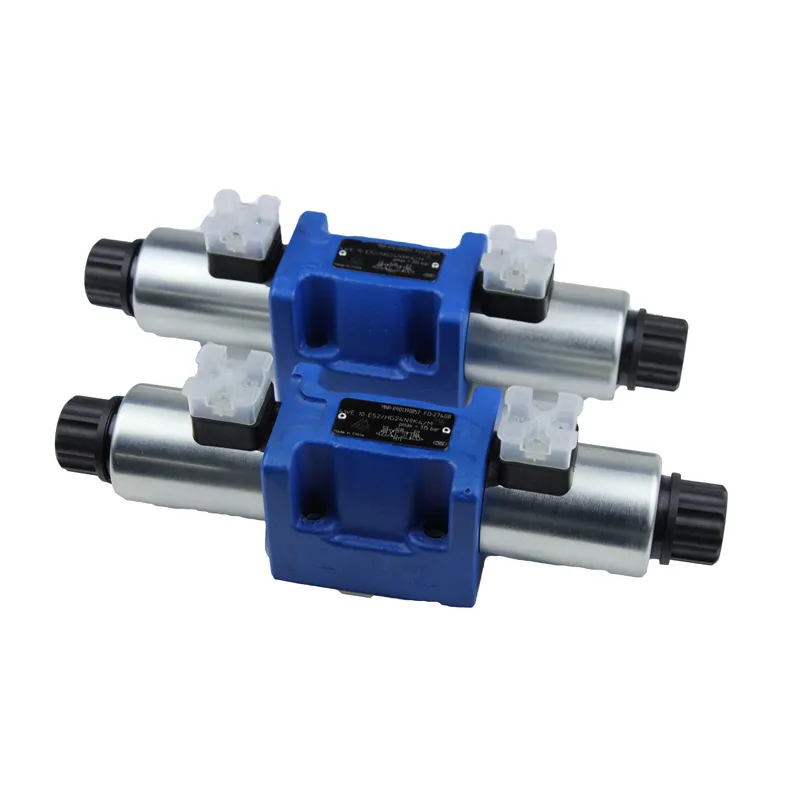
2 way 2 position hydraulic solenoid valve are basic components of automation used to control fluids and are actuators; they are not limited to hydraulics, pneumatics. Solenoid valves are used to control the direction of hydraulic flow. We generally control factory mechanisms with hydraulic cylinders. Therefore, we use 2 way 2 position hydraulic solenoid valves.
The working principle of the solenoid valve is as follows: The solenoid valve has a closed cavity. This cavity has holes that open to different oil pipes in various positions. In the middle of the cavity is the valve body, with two solenoids on either side. When we energize the magnet coils on one side, it attracts the valve body to that side. This controls the movement of the valve body to block or allow flow through different discharge holes.
The inlet holes remain open at all times, allowing hydraulic oil to enter different discharge pipes. The oil pressure then pushes the cylinder piston, which drives the piston rod and, in turn, moves the mechanical device. Then through the oil pressure to push the cylinder piston, piston and drive the piston rod, piston rod drive mechanical device movement. In this way, by controlling the current of the solenoid to control the mechanical movement.
Solenoid valves, both domestic and foreign, can be categorized into three types based on their action: direct-acting, recoil, and pilot-operated. We can further divide recoil solenoid valves into diaphragm-type recoil solenoid valves and piston recoil solenoid valves. We can divide pilot-operated solenoid valves into pilot-operated diaphragm solenoid valves and pilot-operated piston solenoid valves. Additionally, solenoid valves can be classified based on their seat and sealing material into soft sealing solenoid valves, steel sealing solenoid valves, and combinations of these types. Sealed solenoid valve, steel sealed solenoid valve, semi-steel sealed solenoid valve.
When the pneumatic system becomes more complex, the need for greater adaptability of pneumatic valves, and such valves provide such flexibility. In the fluid power field, we refer to these valves as ‘five-port four-way valves.’ The valve uses a common inlet pressure source and two exhaust ports, allowing us to control the exhaust separately from each outlet of the valve.
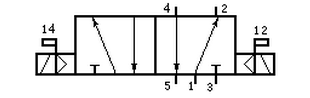
As the diagram shows, we use 1 as the inlet tube, 2 and 4 as the outlet tubes, and 3 and 5 as the exhaust tubes. When we energize the 12 coil, the valve moves to the right valve position. In this position, we let the inlet air exit from port 2 through the valve, and we discharge the air from tube 4 through port 5 of the valve. When we energize the 14 coil, the valve moves to the left valve position. In this position, the inlet air exits from port 4 through the valve. Meanwhile, we discharge the air from tube 2 through port 3 of the valve.
Three-position five-way valves are always double electric control; they cannot be single electric control. Their principle is almost the same as that of two-position five-way valves. The main difference is that in the stop position (with no air pressure at the inlet), the valve is in the middle position. There are generally three options for this middle position: seal, pressure, and drain.
Contact Zhuo Yi Control Technology for the latest production technology!