3D Printing Has Disruptive Impact on Hydraulic Valve Block Processing
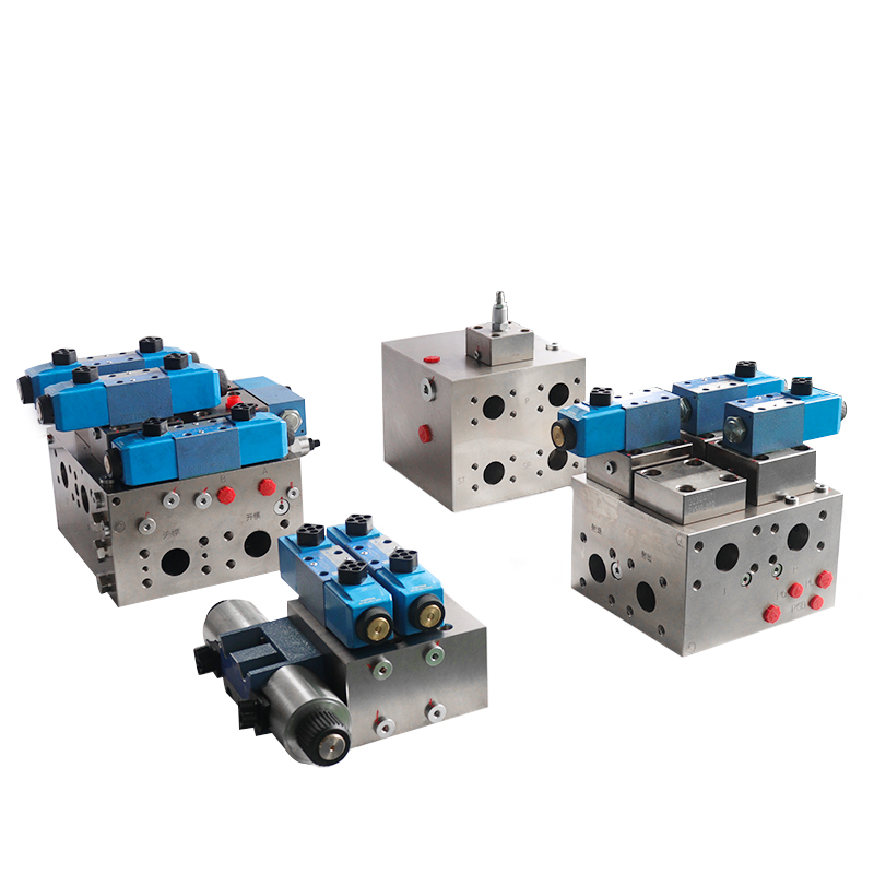
3D printing in hydraulics can include hydraulic component parts (see Figure 26-307), hydraulic valve blocks (see Figure 26-308), and sand patterns for hydraulic casting. One of the focuses is the production of hydraulic valve blocks using 3D printing. The 3D printing of hydraulic cartridge valve blocks is the most representative and successful example of 3D printing in industrial applications. Because of the use of 3D printing, for the cartridge valve block processing results are very significant.
These results show that designing a very complex internal flow path can significantly reduce weight and improve the power-to-weight ratio of hydraulic components. This design simplifies and speeds up processing, making it efficient and cost-effective. It optimizes the shape of the hydraulic flow path, reducing both frictional resistance and local resistance, thereby lowering the power loss caused by the hydraulic flow path. It also directly connects the CAD design and CAE processing of the valve block, achieving a modernized processing method.The best means. In short, for the valve block processing technology to bring disruptive changes.
3D printing for enterprise production benefits can be briefly listed as follows.
1) design freedom, personalised, simplified, lightweight, assembly-free design.
2) no mould, can be quickly iterative and flexible prototype manufacturing.
3)Shorter lead times, with manufacturing times from weeks to days, including favourable maintenance contingencies.
4)Energy efficient.
5)Valve body internal flow path optimisation, reduced pressure loss in the valve body, reduced hydraulic energy loss.
6)Reduced process plugging and also reduced possible leakage points.
7)Design freedom with more exploitable internal and external part geometries.
8)Design optimisation and mass reduction.
9)Higher functional integration and smaller size.
10)Better realisation of the control of mechanical characteristics.
At present, domestic and foreign research and development in additive manufacturing (AM) is very active, such as Bosch Rexroth is developing 3D printing hydraulic system, especially the servo valve in it. Project partners include Germany’s famous machine tool family business through fast (TRUMPF) and powder material manufacturing experts Heraeus (Heraeus). China’s hydraulic enterprises have also been applied in this area, such as Sykes Hydraulic Technology Co.
However, many challenges remain in the current development. In addition to the efficiency of 3D printing technology itself and the challenge of quality consistency, certification poses another difficulty. Chinese enterprises still lack a complete set of ideas on how to meet the complexity of applying 3D printing technology to create hydraulic products under complex and harsh conditions. The industry needs to build a comprehensive public service system as soon as possible. This will help make this new technology a tool for advancing productivity. The industry needs to build a public service system to make this new technology a tool for productivity development.
Currently, the application of hydraulic valve block additive manufacturing is still in the design verification stage of new product development. It is also used for single-piece small batch production and the manufacturing of special complex parts. Additionally, additive manufacturing is employed in rapid mold production. From the perspective of 3D printing manufacturing development, the technology will play a significant role in the future. It will become a means of processing hydraulic integrated valve blocks in batch production. Compared to traditionally manufactured hydraulic parts, metal 3D printing has made significant improvements in aerospace hydraulics. The earliest adoption of this technology led to a reduction in the weight of the main flight control hydraulic part. Additionally, it resulted in the elimination of 10 parts (see Figure 26-308c).


Impact of 3D printing on the overall design process of a hydraulic valve block and its fabrication
The hydraulic integrated block consists of a valve body with complex flow paths. Internally, it includes oil holes, positioning holes, connecting screw holes, and block mounting holes. Additionally, the block features cartridge valve plug-in mounting holes and lateral oil passages for the cartridge valves. At the same time, in order to ensure the correct connection of the hole without interference, sometimes also set up a number of process holes.
Hydraulic valve block design should meet the installation constraints, connectivity constraints and processing constraints. The outer surface of the block should provide enough installation space for the valve components, ensuring no interference between them. All holes must meet the requirements for connectivity and non-connectivity. It is important to ensure the safety of the wall thickness. Each hole’s diameter and depth should fall within the machinable range. Hydraulic valve block design guidelines is to meet these three constraints under the conditions of the oil circuit is simple, small size, light weight.
Conventional hydraulic valve block processing requires pretreatment, machining, deburring, cleaning and other processes (see Figure 26-309a). We conduct pre-processing mainly to inspect or perform non-destructive testing on the valve block material. This step ensures that the internal structure of the material is dense. It also verifies that the material is free from trachoma and entrapment. During machining, we roughly shape the valve block by first milling, planing, and performing other processes on the rough blank.
We then use pliers for scribing and control the roughness of the valve block surface to prevent issues such as leakage. After machining, we deburr the valve block to ensure its smoothness. In the cleaning phase, we use anti-rust cleaning fluid and apply a certain pressure to clean the valve block’s blind holes and other parts, avoiding any residual dirt and debris.In traditional machining processes for hydraulic valve blocks, we encounter issues such as cumbersome clamping. We also face difficulties in controlling shape and position tolerance.
Additionally, there are high requirements for surface roughness.We perform drilling, expanding, boring, reaming, and other processes on the holes, making the process complex and delicate. The hydraulic integrated block has a large size with crossed and mingled orifices, making processing more difficult. Traditional processing results in a cross-shaped flow channel in the completed hydraulic integrated block. This design increases local damping and inevitably raises hydraulic loss.

A higher degree of design freedom is gained through 3D printing technology. The design of 3D printed valve blocks allows for innovation in block design techniques. We can optimize internal flow paths without having to consider the design constraints of cross-drilled holes. Since 3D printing involves layering metal powders (see Figure 26-309b), we can pre-optimize the design of the internal flow paths and design the cross corners as rounded bends. This approach reduces the damping of the flow paths and minimizes localized losses in the hydraulics.
We also make the volume of the entire valve block smaller than in traditional designs, and we can avoid potential leakage at the valve block bonding surfaces. 3D printing processing and manufacturing also avoids problems such as difficult-to-control shape and position tolerances. The shape and position control requirements are basically satisfied. Additionally, 3D printing eliminates the clamping issues associated with traditional machining. It also reduces the unnecessary mass of the metal, aside from the manifolds, achieving a lightweight valve block.
Impact of 3D Printing on Design Improvement of Flow Paths in Hydraulic Valve Blocks
In conventional orifice design, it is unavoidable to provide a T- or cross-shaped orifice system crossing to achieve through-put (see Fig. 26-310a). In contrast, in 3D printing it is entirely possible to design on the principle of minimising hydraulic damping of the flow channel (see Figure 26-310b). Figure 26-311 presents the result of comparing the pressure loss of different flow channels at the same flow rate. This result shows that changing the shape of the flow channel in the valve block can reduce the pressure loss of the valve block.


Printing process of universal valve block for hydraulic cartridge valve
(1) Select the appropriate 3D printing equipment and method According to the hydraulic valve block material requirements to select the appropriate 3D printing equipment. The 3D printing technologies used for hydraulic components are as follows:
1) Metal powder injection moulding (MIM) technology is a precision metal working process, which requires a binder with better performance.
2) Metal wire (or pellets) used in fused deposition modeling (FDM) technology follows the same process as general plastic FDM. Both use melt extrusion and layer-by-layer molding. The difference is that most of the consumables in metal FDM consist of a mixture of metal powder and organic binder. 17-4PH and 316L stainless steel is used for binder injection technology and fused deposition moulding technology of the mainstream materials.
3)Binder injection molding (BI) technology is an additive manufacturing method that involves spraying a binder to mold the powder. This technology, similar to many laser sintering techniques that use a powder bed, employs an inkjet print head to spray the binder onto the powder. The powder layers bond together to achieve molding. Early research in this technology focused on sand casting formation.
4) Laser powder bed fusion (LB-PBF) technology, also known as selective laser melting, is a powder bed-based additive manufacturing process. It uses high-energy laser beams to achieve point-by-point scanning of the powder for metallurgical bonding, enabling the printing of high-performance parts. We can use materials such as aluminum alloys, titanium alloys, nickel-based alloys, ferrous alloys, and precious metal alloys. Additionally, we are currently developing other materials, including magnesium alloys. Theoretically, we can process any weldable material with LB-PBF technology, including polylactic acid (PLA) materials, which are thermoplastics made from renewable resources.
Figure 26-312 illustrates the options for processing parts with 3D printing. We find that 3D printing uniquely suits the manufacture of hydraulic valve blocks and hydraulic valve spools. The main applications of 3D printing technology are PBF selective melting metal 3D printing technology, BJ binder jet metal 3D printing technology, in addition to the way through the binder jet 3D printing sand moulds and casting combination.
There is also the choice of laser melting (SLM) technology to manufacture servo valves, the diameter of 30~60um spherical metal powder, using high-precision laser melting. For each process, only a few microns of melting thickness is established. Then build up layer by layer to get the desired chamber.

(2)Hydraulic valve block used in 3D printing material issues Traditional cartridge valve block materials are roughly the following categories: cast iron, forged steel, profiles, stainless steel and aluminium alloy. Castings may not fit closely, and thin walls can easily leak. Generally, we do not select castings. Instead, we often use Q235A plate and 35 forged steel. When the requirements are not high, we might also use 45 or 50 die steel plates or high-quality carbon structural steel for cutting and production. The general size should not be too large, and the pressure application can exceed 31.5 MPa. We commonly use aluminum alloys such as 6061-T6, 7075-T6, and 2A12.
We generally use these aluminum alloys in medium and low pressure situations below 25 MPa because their structural strength has limitations. Based on the requirements of the usage scenarios, we also use stainless steel to produce the valve block body. For example, water hydraulics or water-based hydraulic media on the use of such materials as valve body materials.
From a 3D printing point of view, valve blocks in hydraulics require forging-grade properties.3D printing can produce stainless steel parts, ranging from AISI 304 to 316L. It can also handle aluminum, titanium, and nickel-based alloys. Additionally, 3D printing equipment can produce some new materials in small batches. Materials for hydraulic products must be strong and corrosion-resistant enough to safely handle the high pressures of hydraulic systems. Materials available include carbon steel, stainless steel and aluminium. These materials include stainless steel such as AISI304, AISI316L, and 17-4PH. They also include aluminum alloys like AISi10Mg. Additionally, we use titanium alloys such as Ti6AI4V, high-temperature nickel-based alloys like IN625 or IN718, and martensitic ageing steels. We use titanium alloys for printing because of their lightweight, stable mechanical properties, and good corrosion resistance.
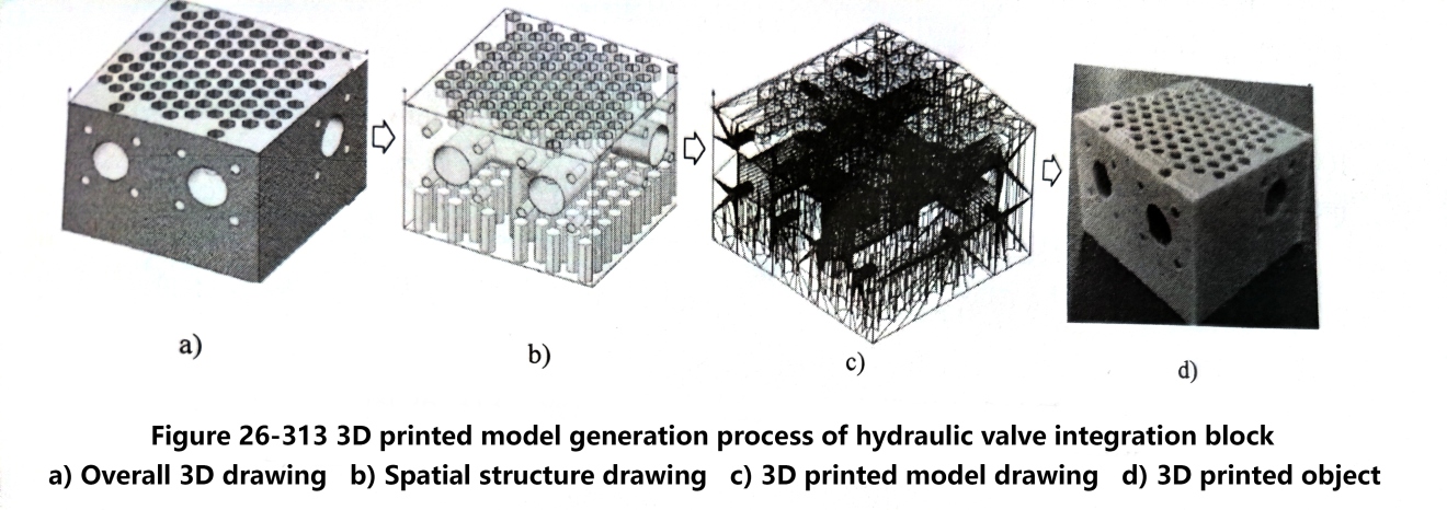
(3) Hydraulic valve integrated block structure model data conversion and detection Based on the characteristics of 3D printing, it is necessary to use computer-aided design software to achieve the hydraulic valve integrated block structure of the 3D model design diagram. The process of generating the 3D printing model for the hydraulic valve integrated block is shown in Figure 26-313. Figure 26-313a displays the overall three-dimensional map. Figure 26-313b shows the spatial structure of the map.
To proceed with the next operation on the hydraulic valve integrated block structural model, you need to design the SolidWorks three-dimensional graphic files. Convert these files to STL format. We save the 3D model in STL format, which uses a triangular mesh to represent the various faces of the hydraulic valve block structure. Figure 26-313c shows the 3D model of the hydraulic valve block in STL format. This is the first step in 3D printing. After you convert the model, import the model file into the appropriate software for integrity testing. If the test reveals no problems, you can proceed to the next step. 3D printing of the physical object is shown in Figure 26-313d.
(4) Introduce the model slicing and set the moulding direction Before slicing, we should test and repair the model file into the technology there is no closed ring and ambiguity phenomenon. Put the saved stl file into Netfabb software for detection, the detection results are shown in Fig. 26-314.
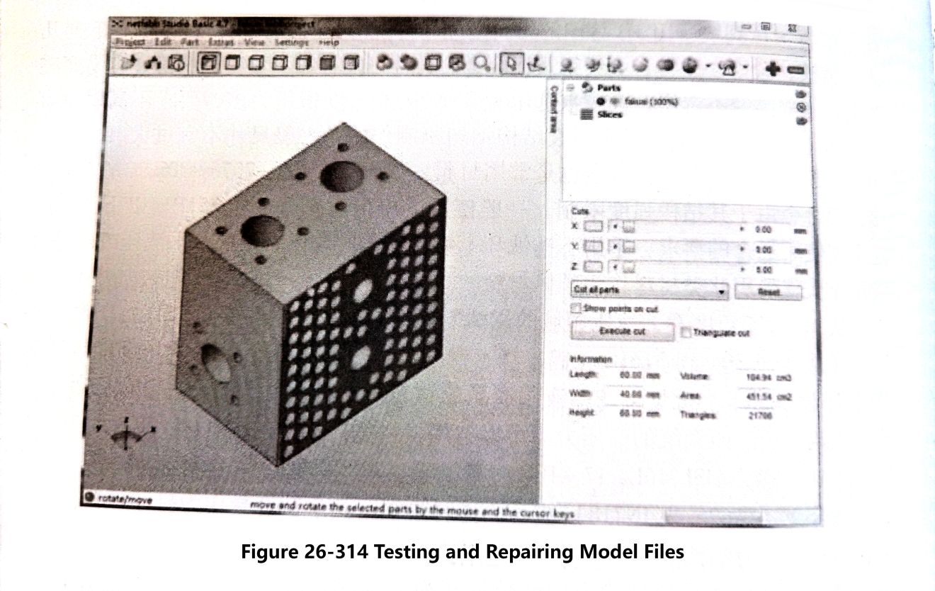
After we test the model file and find no problems, we can import the model slice into the 3D printing software to prepare for printing. After importing into the software, the right side of the computer display will show the parameter setting options. You can set the print quality, speed, hot bed temperature, and other parameters there. The left side shows the 3D view of the hydraulic valve block, where you can drag the model to print. The left side displays a 3D view of the hydraulic valve block, allowing you to drag the model to perform basic operations such as moving, scaling, and rotating it.
In addition, setting the forming direction is very important. It affects how well we can save printing material. It also impacts how much we can shorten the printing time. For the product characteristics of the hydraulic valve integrated block, you do not need to set support for the whole structure. However, you need to add appropriate support for the overhanging surface of the aperture. This step ensures balanced printing throughout the process. After printing, you can completely remove the support material. First, configure the corresponding settings. The system will then save the file and convert it into the relevant code. Next, the system will deposit the file into the SD card of the 3D printer. This process completes the slicing and prepares the printer to start printing.
(5) Hydraulic valve integrated block model printing and shaping Set the diameter of the print material to 1.75 mm and the flow rate to 100%. Adjust the print layer thickness between 0.1 mm and 0.3 mm. When using a layer thickness of 0.1 mm, the printed entity will achieve higher accuracy and surface quality. However, the printing time will be very long, approximately 9 hours and 59 minutes. The consumables will amount to 24.91 meters, and the finished product will weigh 748 grams.Insert the prepared SD card into the 3D printer. Perform pre-printing debugging and preheat the hot bed and printhead. The system will automatically add the set support. Finally, start printing the hydraulic valve integrated block according to the original model setup.The result is shown in Figure 26-313d.
You should note that when printing the hydraulic valve block, you must maintain the installation position requirements for the valve block inlet and outlet. You also need to ensure the machining allowance design. The design of the internal flow path curvature will depend on your choice of 3D printing materials and printing process. For example, the Electron Beam Melting (EBM) process using the titanium alloy Ti-6Al-4V allows designers greater freedom in the size of the circular channel. This freedom surpasses what they can achieve using a laser powder bed. Additionally, designers can produce the part without a support structure.
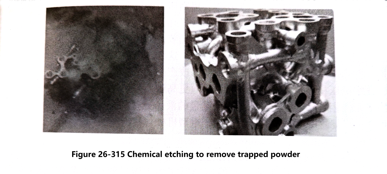
In powder-related 3D printing, we also need to consider removing trapped metal powder that remains in the channel. Later, we may require a CT scan to verify whether we have removed all the powder from the channel. If trapped powder is present, the method of removal is chemical etching (see Figure 26-315). Chemical etching removes most of the trapped powder and can also significantly improve surface roughness. However, for powders that chemical etching still cannot remove, designers can add additional powder removal ports to facilitate powder removal. Additionally, you can ease the machining of the ports at a later stage by moving some passages during the design process. This adjustment allows the fixture to remain on the bottom of the part. As a result, you can machine all of the ports on the hydraulic valve block in a single clamping setup using a 5-axis machine.
Contact Zhuo Yi Control Technology for the latest production technology!