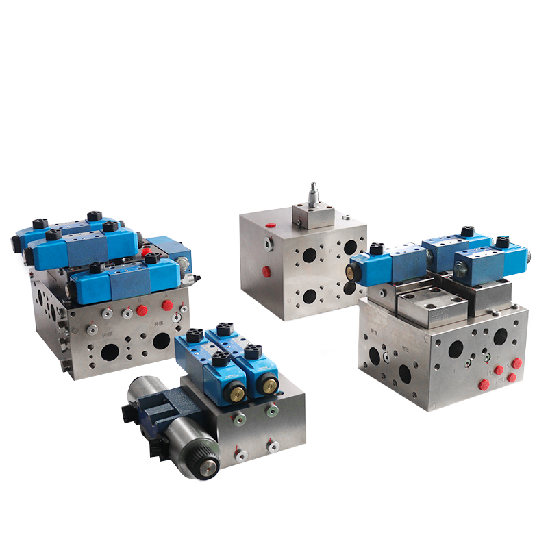
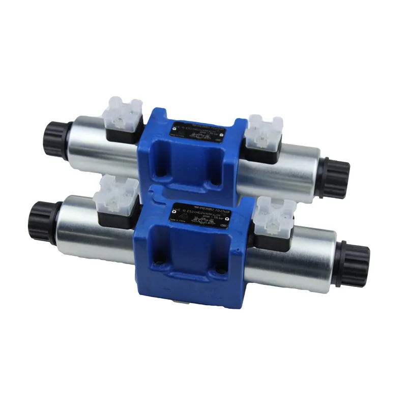
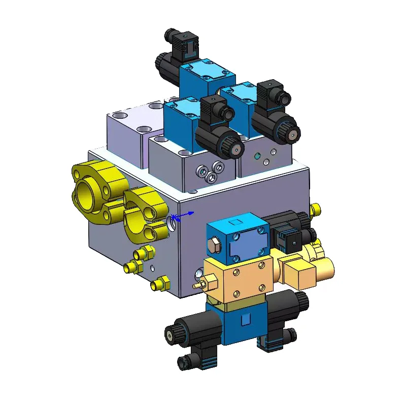
A hydraulic control valve block is a component that manages and directs hydraulic fluid flow by integrating multiple valves and control mechanisms into a single, compact unit.
Hydraulic control valve block in the hydraulic system can start, stop, direction of movement, speed and output force or torque of the actuator to regulate and control. Its working principle is: through the reception of external signals, by the relative movement between the spool and the valve body, change the size of the valve area, to achieve the regulation and control of the fluid. We can divide valves into three categories based on their function: pressure control valves, flow control valves, and directional control valves. In addition, it can also be classified according to the control mode, control signal, connection form, structure form and so on. This article focuses on the form of connection in accordance with a brief introduction.
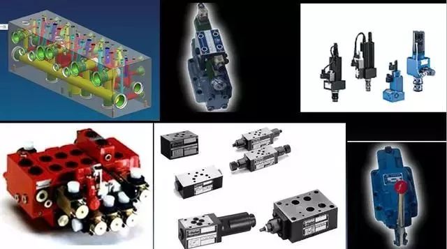
Classification by function
The following table shows the classification according to function and use.
| Valves | Valve type | Explaination |
| Pressure Control Valves | Relif valves,pressure reducing valves, sequence valves,counterbalance valves,electro-hydraulic proportional relief valves,electro-hydraulic proportional pressure reducing valves | Electro-hydraulic servo valve according to the different forms of feedback,can form electro-hydraulic servo control valve,pressure control valve,pressure-flow control valve |
| Flow Control Valves | Throttle valve,speed control valve, diverter valve,collector valve, electro-hydraulic proportional throttle valve,electro-hydraulic proportional flow valve | |
| Dirextional Control Valves | Check valve,pilot operated check valve, directional valve,electro-hydraulic proportional directional valve | |
| Compound Control Valves | Electro-hydraulic proportional pressure-flow combination valves | |
| Special valves for construction machinery | Multi-way valves,flow regulator valves |
Classification according to the connection form
We can divide the connection forms into tube type, plate type, stacked type, integrated block type, plug-in type, piece type, and other types.
(1) Tubular
The diagram below shows a one-way throttle valve with a tubular connection. We throttle flow from A to B and allow unidirectional flow from B to A.
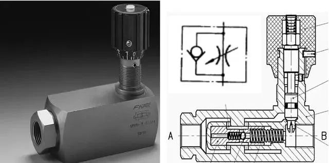
In tube connection, we connect the pipeline through threads. Although the structure is simple, the element arrangement becomes too dispersed, resulting in more leakage points. Disassembly and installation are inconvenient, so this method is used less frequently.
(2) Sheet connection
A piece connection valve combines several side-by-side piece valves. These valves share P and T orifices, with each valve controlling a set of actions. We seal the first and last sides with a cover plate and fasten them using a long screw connection. The whole block integrates most of the actions of the hydraulic system, and the structure is more compact. But between the piece and the piece may cause leakage, replacement trouble, and the number of valves can not be too much.

(3) Board connections, stacked connections and integrated blocks
We mount the valve on a base plate in the plate connection. The valve’s oil port leads through an orifice in the base plate, and we connect the line to the outlet of the base plate.

We find plate connections easy to assemble and disassemble. Additionally, we have standardized the size of the base plate interface for valves of different diameters.

Multiple valves can be stacked on the base plate, called stacked. Stacked valves are widely used in construction machinery.

The integral block type, also referred to as a valve block, is a rectangular body. It has interconnecting orifices drilled on each face. This design replaces complex plumbing connections. The orifices on the mounting surface of the valve provide standard base plate connections for mounting plate or stacked valves. The block type avoids the disadvantages of piping connections that are prone to leakage and takes up less space. The diagram below shows an integrated block type connection.

The picture below shows the internal aperture of an integrated block.

(4) Cartridge type
The cartridge type inserts the valve into the integrated block in the form of a spool and sleeve with a functional cover.

By other means
Categorised by control method in the table below:
| Valves | Description |
| Manual control valves | Handles and handwheels,pedals,levers |
| Mechanical control valves | stops and bumps,springs |
| Hydraulic control valves | Control by liquid pressure |
| Electric control valves | Control by common soleniod,proportional soleniod,force motor,torque motor,stepping motor,etc. |
| Electric-hydraulic control valves | Combined control by electric control and hydraulic control |
We can divide valves based on the form of control signals. The categories include switching fixed-value control valves, analog control valves, and digital control valves. We can also classify valves based on their structure into: slide valves, cone valves, ball valves, nozzle flapper valves, and others.
Contact Zhuo Yi Control Technology for the latest production technology!