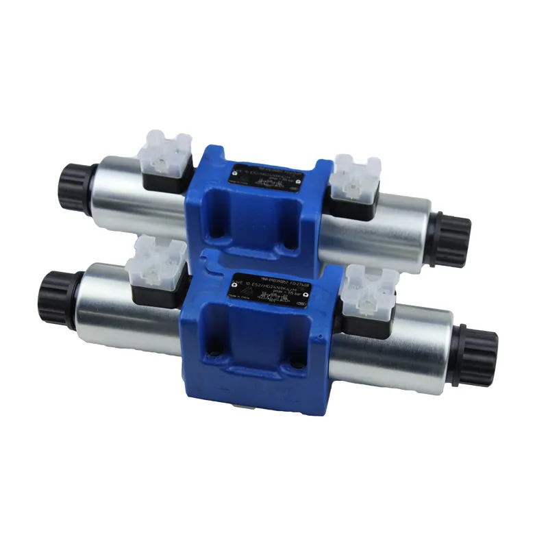
The control element in an electro-hydraulic proportional control system is an electro-hydraulic proportional valve. It accepts the instruction of the electric signal, and continuously controls the pressure, flow rate and other parameters of the system, so that it changes proportionally with the input electric signal. Electro-hydraulic proportional control system can be divided into electro-hydraulic proportional closed-loop control system and electro-hydraulic proportional open-loop control system according to the output parameters with or without feedback. Open-loop system generally consists of control devices (proportional amplifiers and proportional valves), actuators (hydraulic cylinders or hydraulic motors), energy devices (quantitative hydraulic pumps, variable hydraulic pumps or proportional variable hydraulic pumps), etc.; Closed-loop system in addition to the device constitutes an open-loop system, there is a feedback detection device. Closed-loop system than the open-loop system has a faster response and higher control accuracy and anti-interference ability.
The outstanding advantage of electro-hydraulic proportional control system is that it can significantly simplify the system to achieve complex program control, and can use electro-hydraulic combination to improve the level of product mechatronics, to facilitate the signal transmission over long distances and computer control.
Electro-hydraulic proportional control system can control the pressure, force, torque, position, angle control, but also can control the speed, speed.
I. Plastic injection moulding machine electro-hydraulic proportional control system
Plastic injection moulding machine, also known as injection moulding machine, is used for thermoplastic plastic forming process. It heats and melts granular plastic, injects it quickly into the mould cavity at high pressure, and after a certain period of holding pressure and cooling, it becomes a plastic product. In the plastic machinery, the injection moulding machine is the most widely used.
The working cycle of injection moulding machine is as follows.
1) Close the mould The moving template moves forward quickly, close to the fixed template, the hydraulic system turns to low pressure, slow speed control. In confirming that there is no foreign matter in the mould, the system turns to high pressure, so that the mould is closed.
2)Injection Seat Move forward nozzle and mould close.
3)Injection The injection screw injects the melt from the front end of the machine brief into the mould cavity at a certain pressure and speed.
4)Holding pressure The injection cylinder holds pressure on the melt in the mould cavity for replenishment.
5) product cooling and pre-moulding: pressure holding is completed, the liquid motor eye screw and backward, the hopper is added to the material is pushed forward typical hydraulic system for pre-moulding. Screw back to a predetermined position, stop turning, ready for the next injection. The products in the mould cavity are cooled and moulded.
6.)Anti-flowing Christmas:When adopting straight-through open type nozzle, the pre-moulding and adding material is finished, make the screw backward for a small distance, reduce the pressure at the front end of the material brief, and prevent the material at the end of the nozzle from flowing out.
7.) Injection seat back: open the mould and eject the product.
8) Ejector cylinder back.
The requirements for the hydraulic system of the injection moulding machine are.
1) sufficient clamping force: melted plastic to 12 ~ 20MPa high pressure into the mould cavity, so the clamping hydraulic cylinder must produce sufficient clamping force, otherwise the mould in the injection from the seam and the plastic products produce overflow edge.
2)Adjust the speed of opening and closing the mold based on the requirements. Use a fast speed to improve productivity when the mold is empty. Use a slow speed when closing the mold to avoid impact and vibration of the machine.
3) enough injection seat moving hydraulic cylinder thrust: to ensure that the injection nozzle and mould gate close contact.
4) Adjustable injection pressure and injection speed to adapt to different plastics, product geometry, mould casting system requirements.
5)To achieve a precise shape, it is important to hold the pressure and adjust the pressure. This ensures that the plastic remains close to the mold cavity. Additionally, during the cooling and shrinking process of the products, the melted plastic can continuously fill the mold cavity to prevent the production of waste products.
6) Smooth product ejection speed.
Figure 10-8 shows the hydraulic system principle of XS-ZY-250A injection moulding machine. The system adopts proportional valve to pressure
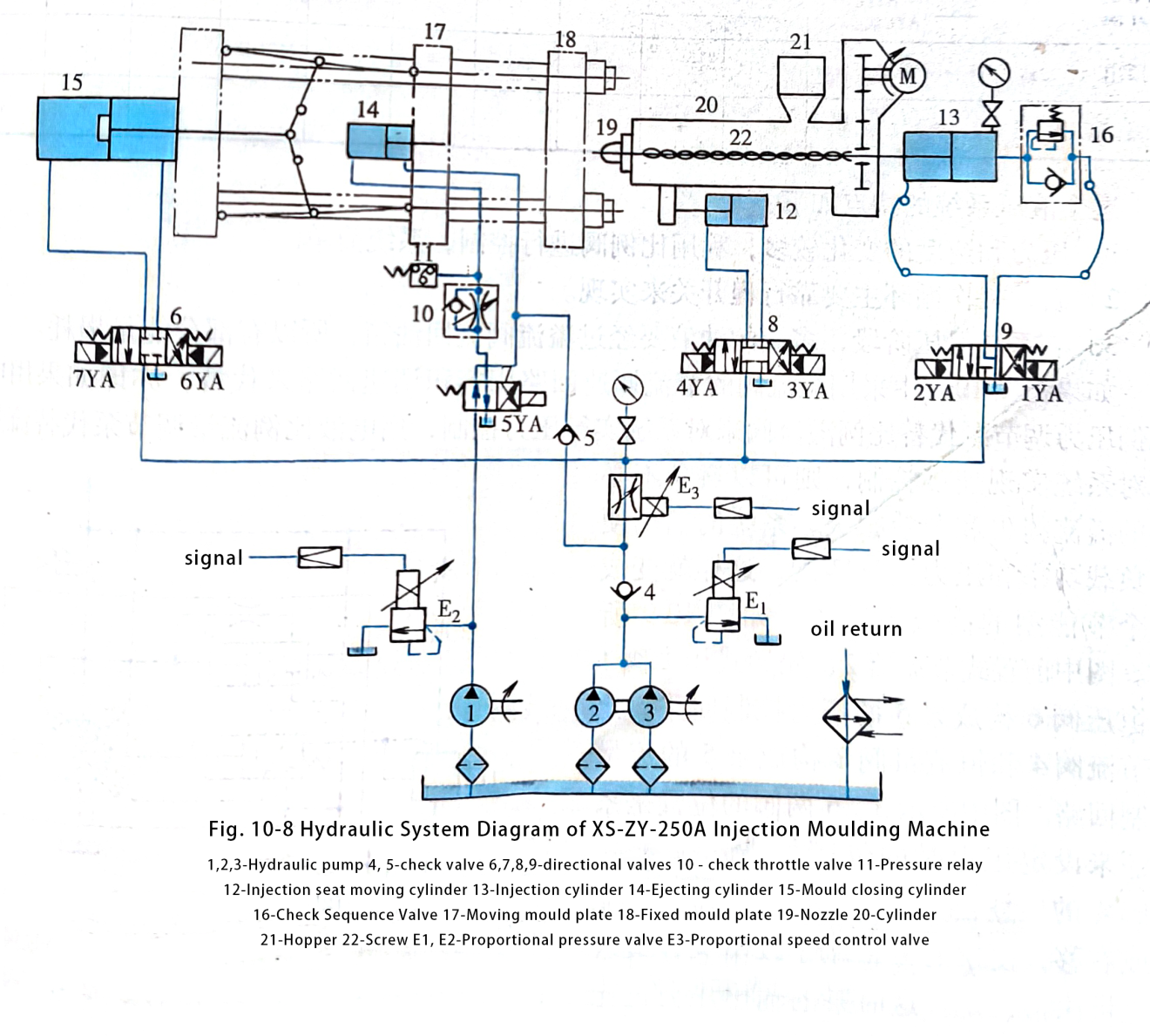
(pressure when opening and closing the mould, moving the injection seat forward, injecting, ejecting, screw backward) and speed (speed when opening and closing, injecting) are controlled, the oil circuit is simple, fewer valves are used, the efficiency is high, and the pressure and speed change is small shock and low noise.
Table 10-5 shows the solenoid in the various stages of power on and off state, as for the work of the oil circuit is not self-evident.
| Table 10-5 Solenoid Operation | |||||||||||
| movement | 1YA | 2YA | 3YA | 4YA | 5YA | 6YA | 7YA | E1 | E2 | E3 | |
| form a mould | Fast mould closing | + | + | + | + | ||||||
| low voltage protection | + | + | + | + | |||||||
| High pressure locking | + | + | + | ||||||||
| Injection Seat Advance | +/- | + | + | ||||||||
| injection moulding | + | + | + | + | |||||||
| keep under pressure | + | + | + | ||||||||
| preform | + | + | + | ||||||||
| Injection Seat Back | +/- | + | + | ||||||||
| mould opening | + | + | + | + | |||||||
| eject | + | + | |||||||||
| Screw Back | + | + | + | ||||||||
The characteristics of this hydraulic system are as follows.
1)More changes in pressure and speed, using proportional valves for control, the system is simple
2)Automatic work cycle is mainly achieved by travelling switches.
3)During the pressure holding phase of the system, the excess oil has to flow back to the tank through the relief valve, so there is some energy loss.
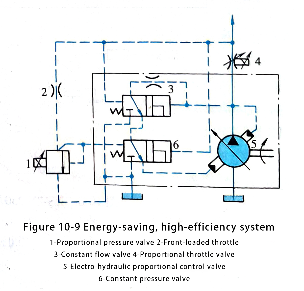
If Figure 10-8 in the use of relief valve throttle speed control circuit with a volumetric speed control circuit instead, that is, if the electro-hydraulic proportional pressure regulator pump instead of proportional relief valve to implement pressure control of the system, electro-hydraulic proportional flow regulator pump instead of the flow valve to achieve speed control of the system, you can avoid unnecessary loss of overflow and throttling loss, the output of the system will be fully matched with the load power and pressure, thus The output of the system is then perfectly matched to the load power and pressure, thus turning it into an energy-saving and high-efficiency system, as shown in Figure 10-9.
In the figure, the front type throttle 2, pilot operated pressure valve 1 and constant pressure valve 6 constitute the pressure control circuit of pump 5. Proportional throttle 4 and constant flow valve 3 constitute the flow control circuit of pump 5.
The position of the two valves 3 and 6 shown in the figure is the position when the system has not yet set the pressure. If the load changes, so that the differential pressure of the valve 4 is large or small, then push the valve 3 left or right, so that the pump displacement is reduced or increased, and ultimately the flow rate to maintain a constant. At this point, the output pressure of the pump is only one differential pressure of valve 4 higher than the load pressure.
During the holding pressure stage, when the system pressure reaches the highest level set by valve 1, valve 6 shifts to quickly reduce the pump displacement to nearly zero. This adjustment forces the pump into a high-pressure, low-displacement operating condition.
Overall, the system effectively coordinates the pump output pressure with the load during the flow control stage. In the pressure control stage, it minimizes the output flow rate to near zero, resulting in minimal power consumption.
This makes the system very efficient.
Ⅱ. CNC bending machine electro-hydraulic proportional control hydraulic synchronous system
Bending machines are pressure processing equipment with a wide range of uses in industries such as construction and decoration. Nowadays, projects are getting bigger and workpieces are getting longer, requiring bending machines to be wider and wider. As a result, operators must pressurize large bending machines with two hydraulic cylinders simultaneously, and controlling the synchronization accuracy is one of the key technologies. Therefore, the traditional bending machine is far from being able to meet the requirements. In recent years, the development of CNC bending machine, with its convenient operation, accurate control accuracy, doubly favoured by users.
Figure 10-10 shows the structure of the CNC bending machine sketch and hydraulic system. In the figure, two hydraulic cylinders 10 control subsystem is identical. Each hydraulic cylinder together with the displacement sensor 11, proportional directional valve 4 and CNC (numerical control system) 12 constitute a full closed-loop position control system. The CNC also controls the synchronised movement of the two pistons, as shown in Figs. 10-11.
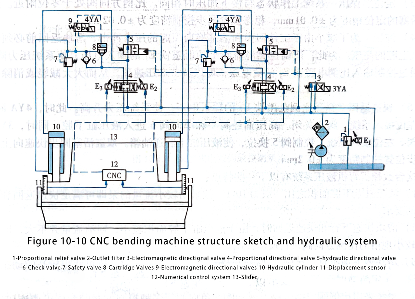
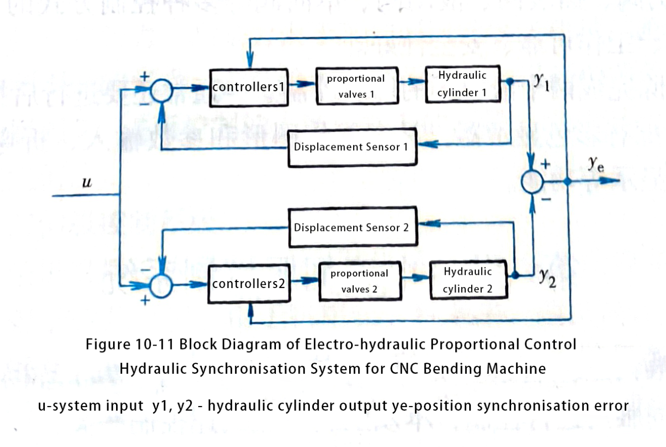
The working cycle of the bending machine slider 13 is as follows: fast downward travelling -> slow downward pressurisation -> positioning, holding pressure -> unloading pressure -> fast return. The slider works as follows.
(1) fast downstream: proportional directional valve 4 solenoid E2 positive voltage, hydraulic cylinder 10 upper chamber oil. At the same time, the solenoid 4YA electrified suction, electromagnetic directional valve 9 right position into the system, cartridge valve 8 open. Hydraulic cylinder lower chamber through the proportional directional valve 4 and the oil tank, the slider rely on self-weight rapid downward movement. The CNC (numerical control system) 12 adjusts the openings of the two proportional directional valves. This controls the oil return from the lower chambers of the two hydraulic cylinders. As a result, the two pistons move downward quickly and synchronously. The dynamic synchronous position control accuracy is ± 0.2 mm. If the oil supply to the upper chamber of the hydraulic cylinder is insufficient, the hydraulic directional valve 5 will replenish oil from the tank.
(2) To slow down the pressure, solenoid 4YA remains energized to create suction, and cartridge valve 8 continues to stay open. Hydraulic cylinder lower chamber oil through the proportional valve back to the tank. At the same time, solenoid 3YA is energized to create suction. Solenoid directional valve 3 shifts to the right position, connecting to the system. This action ensures that hydraulic directional valve 5 no longer connects the upper chamber of the hydraulic cylinder to the tank. High-pressure oil flows through the proportional directional valve 4 to the upper chamber of the hydraulic cylinder. The CNC system adjusts the opening of the two proportional directional valves. This controls the oil inlet to the upper chambers of the two hydraulic cylinders. As a result, the system pressurizes both pistons to move downward slowly and synchronously. The dynamic synchronous position control accuracy is ±0.2mm.
(3) Positioning, pressure: the system working condition is the same as the slow down pressurisation. The proportional directional valve is near the zero position. At this time
The positioning accuracy of the double-cylinder piston is ±0.01mm, and the steady state position synchronous control accuracy is ±0.02mm.
(4) Unloading: To reduce the pressure impact caused by workpiece rebound and piston commutation, you must unload the slider. You should do this before returning to the high pressure of the upper chamber of the hydraulic cylinder. To achieve this, adjust the input voltage of the proportional relief valve 1 solenoid E1 downward. This adjustment will reduce the system pressure. At the same time, you can control the negative voltage of the input proportional solenoid E. This adjustment allows you to control the speed of pressure relief. Thus, the system greatly reduces or eliminates the commutation shock.
(5) Rapid return Increase the input voltage of the proportional solenoid E,to increase the system pressure. At this time, 4YA disconnect valve 9 left position access to the system, valve 8 closed. High-pressure oil through valve 4 and check valve 6 into the lower chamber of the hydraulic cylinder. At the same time, with a 3YA power failure, valve 3 shifts to the left position to access the system. Control valve 5 then changes position, allowing the upper chamber of the hydraulic cylinder to connect to the tank. Double-cylinder piston synchronised fast upward, dynamic synchronous position control accuracy of ± 0.2mm.
This CNC bending machine hydraulic system has some of the following features.
1) The ratio of the area of the upper and lower chambers of the hydraulic cylinder is generally 10:1. As a result, using a smaller flow rate pump can meet the requirements for rapid return and slow pressurization.
2) When the slider moves down quickly and returns quickly, the lower area of the hydraulic cylinder cavity is small. Therefore, the return flow is not large. You can choose a smaller size of the proportional directional valve for the required control.
3) When you slowly pressurize the slider, the proportional directional valve controls the upper chambers of the hydraulic cylinder. It also controls the lower chambers of the hydraulic cylinder simultaneously. This allows the system to achieve high dynamic synchronization accuracy. It also ensures high static positioning accuracy.
4) The system uses proportional valves, cartridge valves, poppet valves, and check valves. These components form a hydraulic circuit with a variety of control modes. This design ensures that the hydraulic system has a simple structure, reliable operation, and good safety.
In addition to completing the synchronous control of the two hydraulic cylinders, the CNC system of the bending machine usually has to carry out the closed-loop control of the servo motor. This servo motor controls the rear stopper. The color monitor equips the CNC system. This monitor displays working graphics and allows parameter input. It also supports bending process parameter calculation and process simulation. Additionally, it offers programming and parameter display functions.
Contact Zhuo Yi Control Technology for the latest production technology!