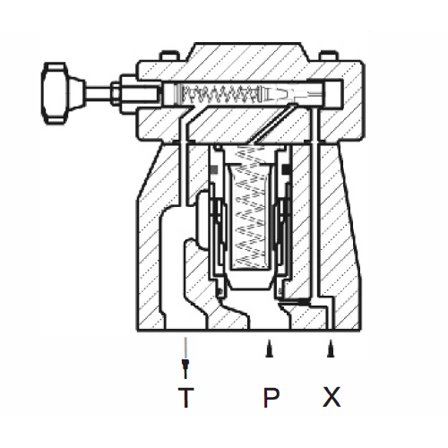
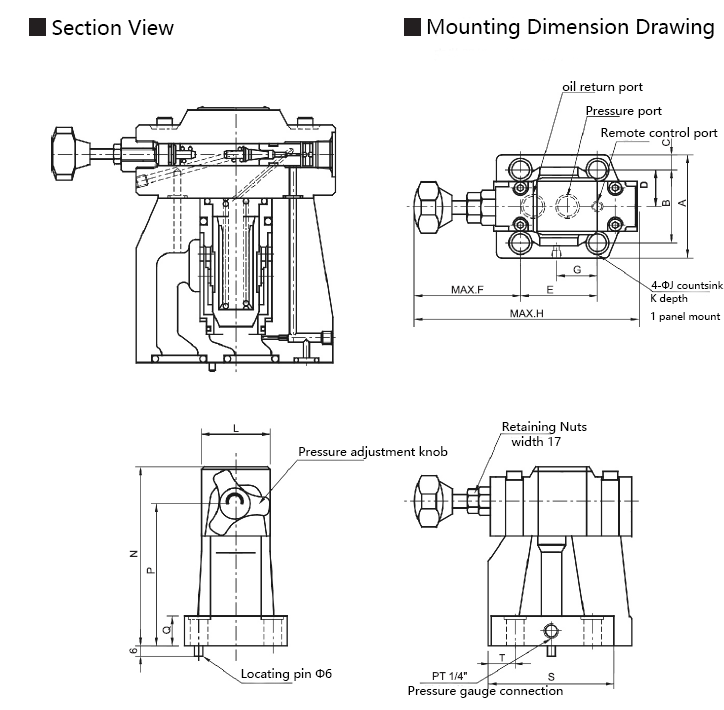
Ordering Model Description:
| HRF | -G | 06 | -1 | -L | -30 |
| Valve Designator | Installation form | Nominal diameter(mm) | Pressure adjustment range(bar) | Adjustment knob position | Design number |
| Low noise pilot operated relief valves | G:Panel Mount | 03:10 06:20 10:32 | 1:7-70 2:35-140 3:70-250 | L:(standard type) Adjustment knob on the T side of the oil return port R:(Customized products) Adjustment knob on the P side of the oil inlet | 30:Standard Type 32:Low Bottom Pressure Type |
Specification:
| Type | Maximum operating pressure (bar) | Pressure adjustment range (bar) | Maximum flow rate (L/min) | Mounting screws |
| HRF-G03 | 250 | 1:7-70 2:35-140 3:70-250 | 100 | 4-M12 x 40L(1/2 x 1 3/5″) |
| HRF-G06 | 200 | 4-M16 x 45L(5/8 x 2″) | ||
| HRF-G10 | 400 | 4-M20 x 60L(3/4 x 22/5″) |
Instructions for use:
Recommended viscosity
Recommended viscosity for normal operation:15~400mm²/s
With a valve with oil damper, the viscosity range must be 20~200mm²/s.
Recommended Fluids
Any of the following hydraulic fluids can be used.
Petroleum-based fluids: Use fluids comparable to ISO VG32 or VG46.
Synthetic fluid: Use phosphate ester fluid or polyol ester fluid. When using phosphate ester fluid, use special Viton seals.
Water-containing fluid:Use water glycol fluid.
Operating fluid temperature
Continuous operating temperature is -15 to +70°C.
Contamination control
Care should be taken to control contamination of the hydraulic fluid, as failure to do so may result in damage to the valve or shorten its service life. Please
ensure that the contamination level is NAS1638-11 grade, and use a 25μm or more precise line oil filter.
Pressure Adjustment
To adjust the pressure, loosen the lock nut and turn the handle slowly, clockwise for pressure increase, counterclockwise for pressure decrease, do not forget
to lock the nut after adjustment.
Return form
If a remote control valve is used to control the pressure, the internal volume of its return pipe is too large and frequency vibration is likely to occur. Therefore,
the length and diameter of the piping should be minimized.
Flow rate selection
When the adjustment pressure will be unstable at small flow rates, the flow rate should be more than 8 L/min when using specifications 03 and 06, and more than 15 L/min when using specification 10.
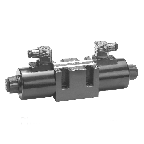
| Hydraulic solenoid valve type comparison table | ||||
| 6-Way Hydraulic Solenoid Directional Valve Model Comparison Table | ||||
| LITAND | YUKEN | Huade | VICKERS | Rexroth |
| SWH-G02-C2 | DSG-01-3C2 | 4WE6E51 | DG4V-3-2C | 4WE6E51 |
| SWH-G02-C3 | DSG-01-3C3 | 4WE6H51 | DG4V-3-0C | 4WE6H51 |
| SWH-G02-C4 | DSG-01-3C4 | 4WE6J51 | DG4V-3-6C | 4WE6J51 |
| SWH-G02-C5 | DSG-01-3C5 | 4WE6F51 | DG4V-3-1C | 4WE6F51 |
| SWH-G02-C6 | DSG-01-3C6 | 4WE6G51 | DG4V-3-8C | 4WE6G51 |
| SWH-G02-C7 | DSG-01-3C9 | 4WE6M51 | DG4V-3-7C | 4WE6M51 |
| SWH-G02-C8 | DSG-01-3C12 | 4WE6L51 | DG4V-3-3C | 4WE6L51 |
| SWH-G02-C8S | DSG-01-3C10 | 4WE6U51 | DG4V-3-31C | 4WE6U51 |
| SWH-G02-B2 | DSG-01-2B2 | 4WE6D51 | DG4V-3-2A | 4WE6D51 |
| SWH-G02-B3 | DSG-01-2B3 | 4WE6C51 | DG4V-3-0AC | 4WE6C51 |
| SWH-G02-B2S | DSG-01-2B2-L | 4WE6Y51 | DG4V-3-2A-L | 4WE6Y51 |
| SWH-G02-B20 | DSG-01-2B8 | 4WE6A51 | DG4V-3-22A | 4WE6A51 |
| SWH-G02-B40 | / | 4WE6B51 | DG4V-3-2BL | 4WE6EB51 |
| SWH-G02-D2 | DSG-01-2D2 | 4WE6b/OF51 | DG4V-3-2N | 4WE6b/OF51 |
| 10-way hydraulic solenoid valve type comparison table | ||||
| LITAND | YUKEN | Huade | VICKERS | Rexroth |
| SWH-G03-C2 | DSG-03-3C2 | 4WE10E51 | DG4V-5-2C | 4WE10E51 |
| SWH-G03-C3 | DSG-03-3C3 | 4WE10H51 | DG4V-5-0C | 4WE10H51 |
| SWH-G03-C4 | DSG-03-3C4 | 4WE10J51 | DG4V-5-6C | 4WE10J51 |
| SWH-G03-C5 | DSG-03-3C5 | 4WE10F51 | DG4V-5-1C | 4WE10F51 |
| SWH-G03-C6 | DSG-03-3C6 | 4WE10G51 | DG4V-5-8C | 4WE10G51 |
| SWH-G03-C7 | DSG-03-3C9 | 4WE10M51 | DG4V-5-7C | 4WE10M51 |
| SWH-G03-C8 | DSG-03-3C12 | 4WE10L51 | DG4V-5-5C | 4WE10L51 |
| SWH-G03-C8S | DSG-03-3C10 | 4WE10U51 | DG4V-5-51C | 4WE10U51 |
| SWH-G03-B2 | DSG-03-2B2 | 4WE10D51 | DG4V-5-2A | 4WE10D51 |
| SWH-G03-B3 | DSG-03-2B3 | 4WE10C51 | DG4V-5-0AC | 4WE10C51 |
| SWH-G03-B2S | DSG-03-2B2-L | 4WE10Y51 | DG4V-5-2A-L | 4WE10Y51 |
| SWH-G03-B20 | DSG-03-2B8 | 4WE10A51 | DG4V-5-22A | 4WE10A51 |
| SWH-G03-B40 | / | 4WE10B51 | DG4V-5-2BL | 4WE10EB51 |
| SWH-G03-D2 | DSG-03-2D2 | 4WE10b/OF51 | DG4V-5-2N | 4WE10b/OF51 |
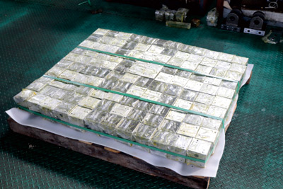
Ensure Quality – Full CNC Machining
We adopt full CNC processing to maximize the elimination of human error, with consistency as high as 98%. Several strict inspection and cleaning procedures and a perfect system guarantee the high quality of the products.
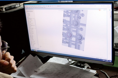
Technology development and design
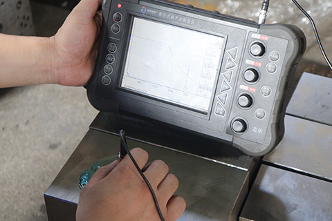
Testing of raw materials
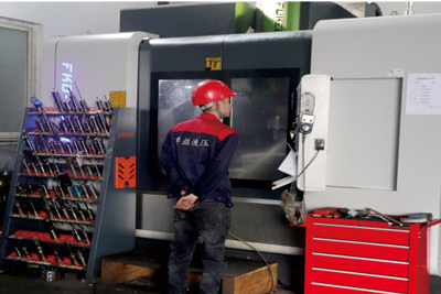
CNC machining
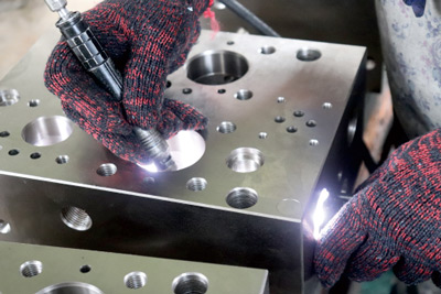
Burr repair
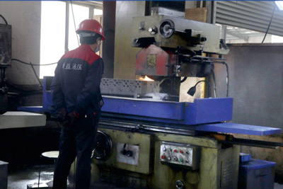
Surface grinding machine
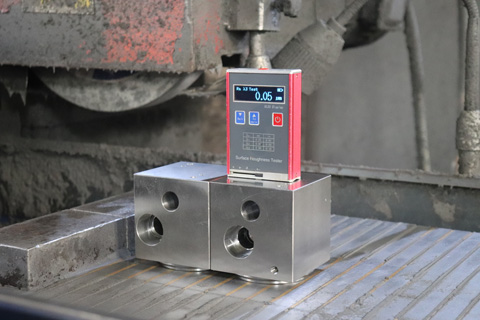
Surface finish detection
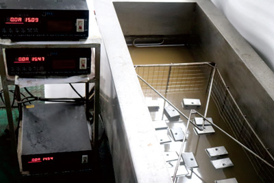
Ultrasonic cleaning
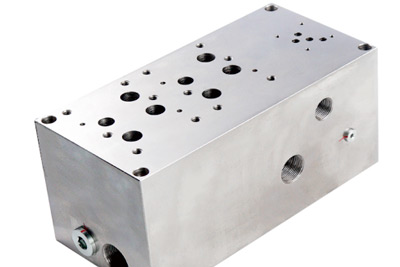
External processing nikel plating
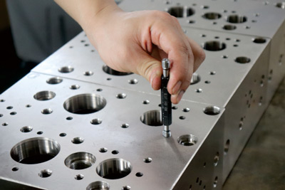
Thread check gauge
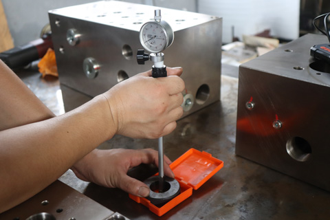
Hole inner diameter dial indicator detection
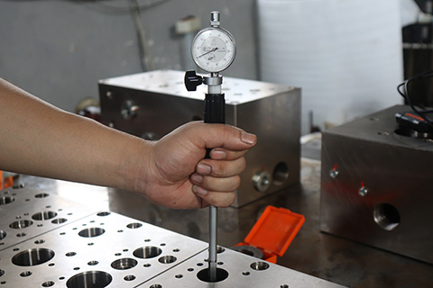
Thread ring gauge detection
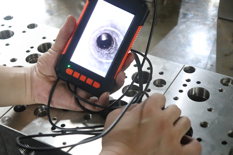
Semi-finished products endoscopic detection
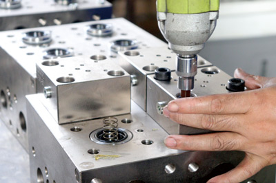
Product assembly
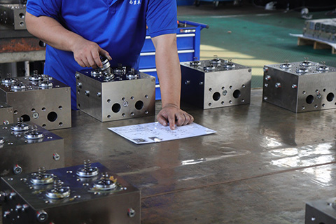
Assembly drawing comparison check