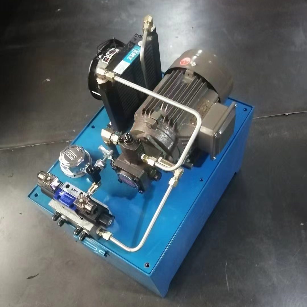
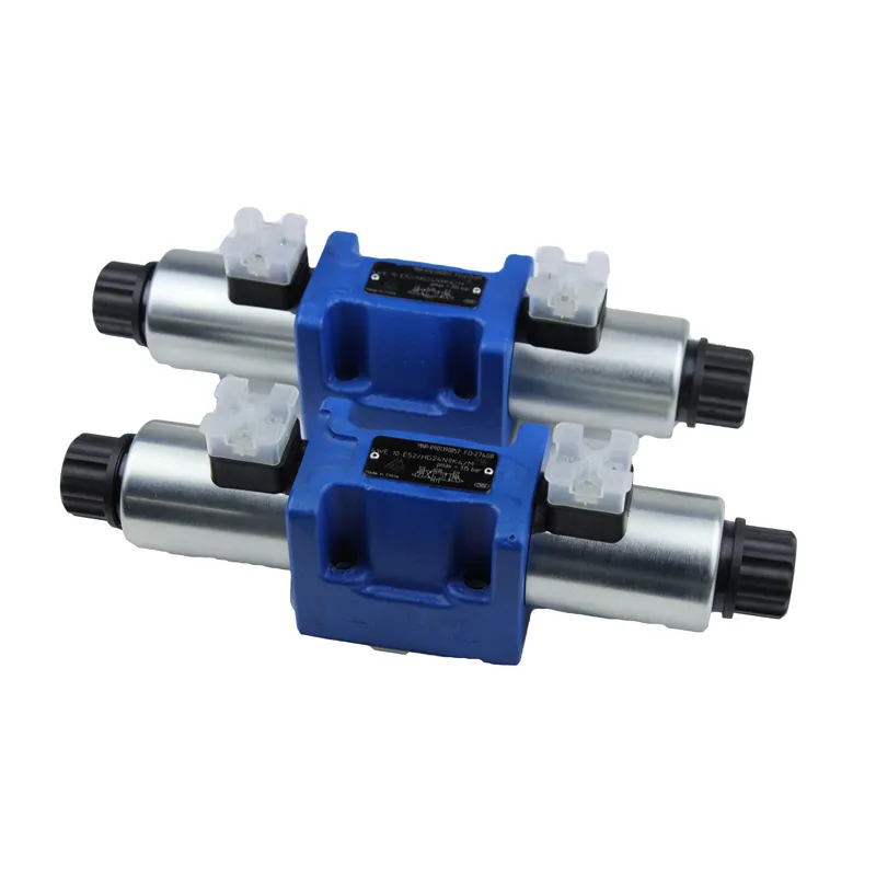
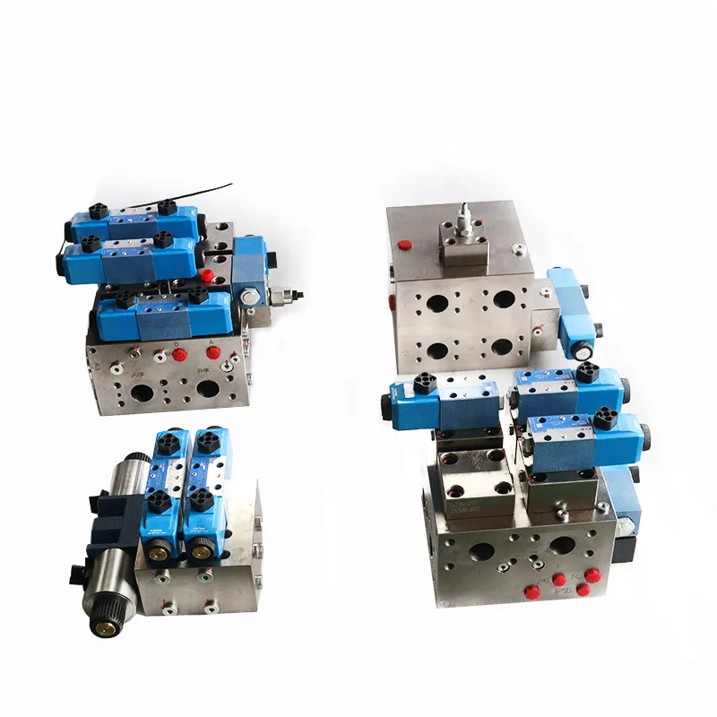
1, the role of the hydraulic diverter block
As shown in the figure, it is a single-pump, two-cylinder system in which a hydraulic diverter block serves the purpose of enabling the gear pump to supply the same flow rate to both hydraulic cylinders so that the speeds of the two actuating elements remain synchronised.
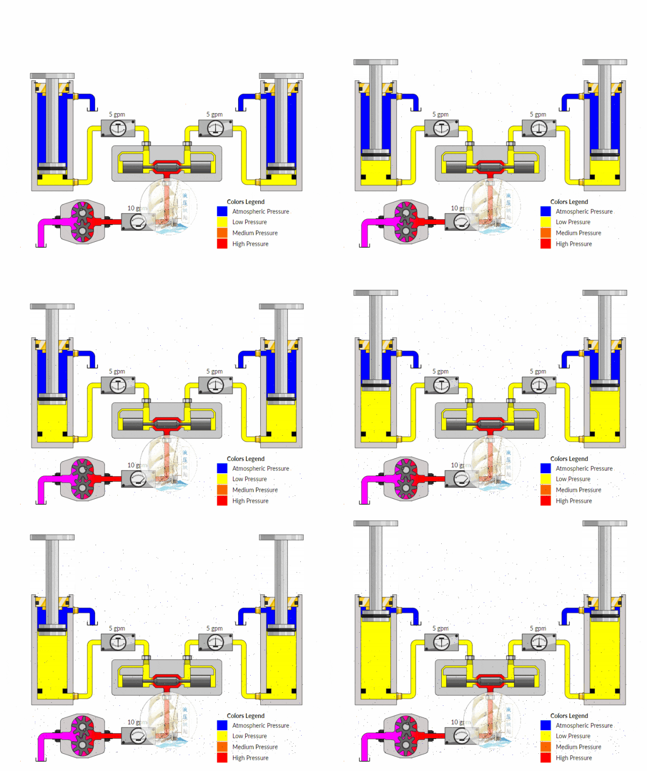
2、Working principle of hydraulic diverter block
Assuming that the inlet pressure of the valve is P0 and the flow rate is Q0, the pressure oil sent out by the gear pump enters the valve body and splits into two paths, passing through two variable throttle holes 1 and 2 respectively;
The oil passing through the variable throttle holes 1 will enter the left hydraulic cylinder from the oil port I. In addition, the load pressure of the left cylinder will be fed back to the left chamber a of the spool through the fixed throttle holes 3;
The oil passing through the variable throttle orifice 2, on the other hand, will enter the hydraulic cylinder on the right side, from the oil port II, and in addition, the load pressure of the cylinder on the right side will be fed back into the chamber b on the right side of the spool through the fixed throttle orifice 4;
If the loads driven by the two hydraulic cylinders are of equal size, the
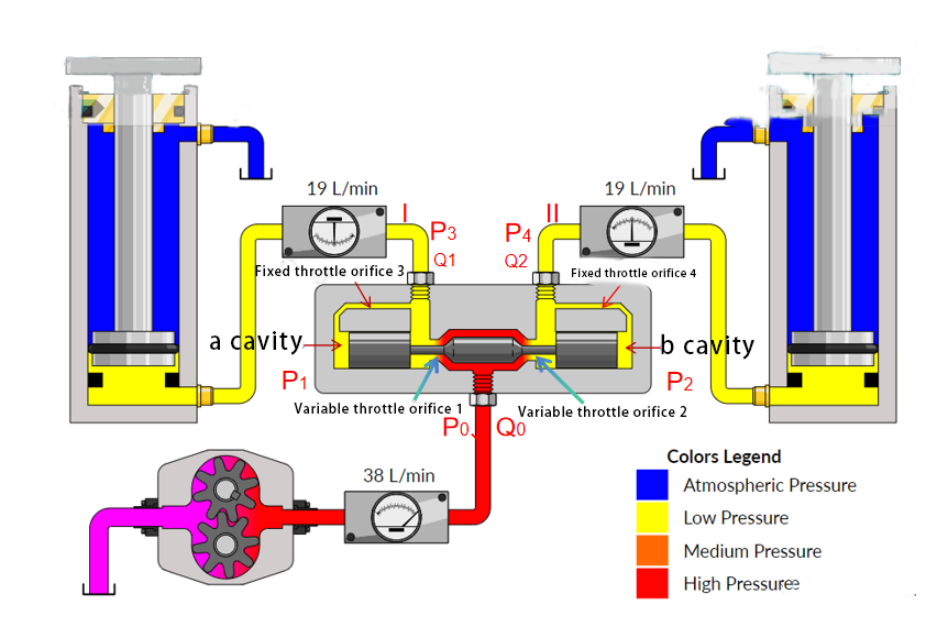
Then the pressures P3 and P4 at the hydraulic diverter block outlets I and II are equal. This is because the two tributary oil passages in the valve are exactly equal in size. As a result, the output flow rates are also equal.
\(Q_1=Q_2=\frac{Q_0}{2} \)
If the loads driven by the two cylinders are not equal, and we assume that the load on the left cylinder is large and the load on the right cylinder is small, i.e. P3 > P4.

We assume that at the moment of load increase on the left hydraulic cylinder, the spool of the hydraulic diverter block has not had time to react and remains in the middle position, and since P0 does not change at this time while P3 increases, the pressure difference 🔺P between the two sides of the left variable throttle orifice 1 decreases accordingly:
\(\Delta P=P_0-P_3\)
Then according to the small hole flow equation
\(Q=K\cdot A\sqrt{\Delta P} \)
The flow rate Q1 through the variable throttle orifice 1 is reduced accordingly. Since the total flow rate Q0 is constant and Q1 is reduced, the flow rate Q2 through the variable throttle orifice 2 is increased, which is obviously not the desired result.
Well soon, the increased value of the load pressure on the left hydraulic cylinder due to the increased load was fed back into the left a-chamber. This caused P1 to rise. Meanwhile, the pressure P2 in the b-chamber on the right side of the spool did not change. Consequently, the slide valve spool was pushed to the right side.
This results in an increase in the through-flow area of the variable throttle orifice 1. Additionally, the through-flow area of the variable throttle orifice 2 decreases.
In this way, the through-flow area A of variable throttle port 1 increases. The increased load initially reduces the flow rate by Q1, but this portion of the flow rate starts to increase again. Since the total flow rate Q0 remains unchanged, the flow rate Q2 through variable throttle port 2 decreases.
\(Q_1\uparrow ,Q_2\downarrow \)
Until they are equal again
\(Q_1=Q_2\)
At this point, the spool reaches a new equilibrium position and stabilizes. This ultimately ensures that the flow to the two cylinders is once again equal. As a result, the system synchronizes the speed of the two cylinders of the same construction size.
Contact Zhuo Yi Control Technology for the latest production technology!