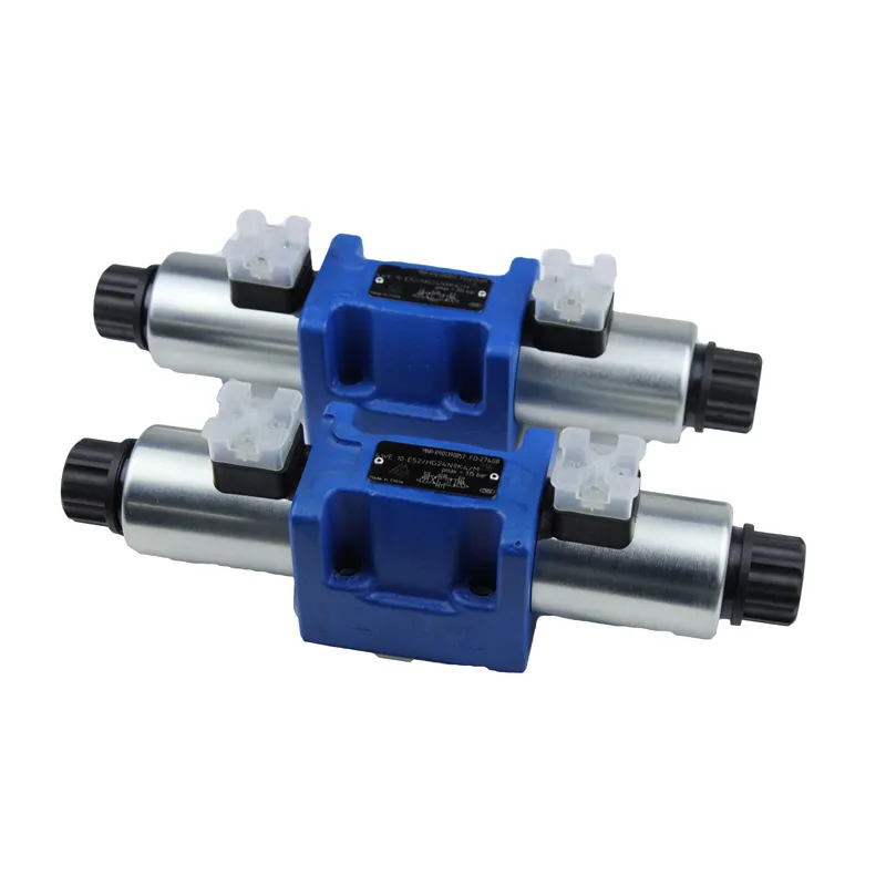
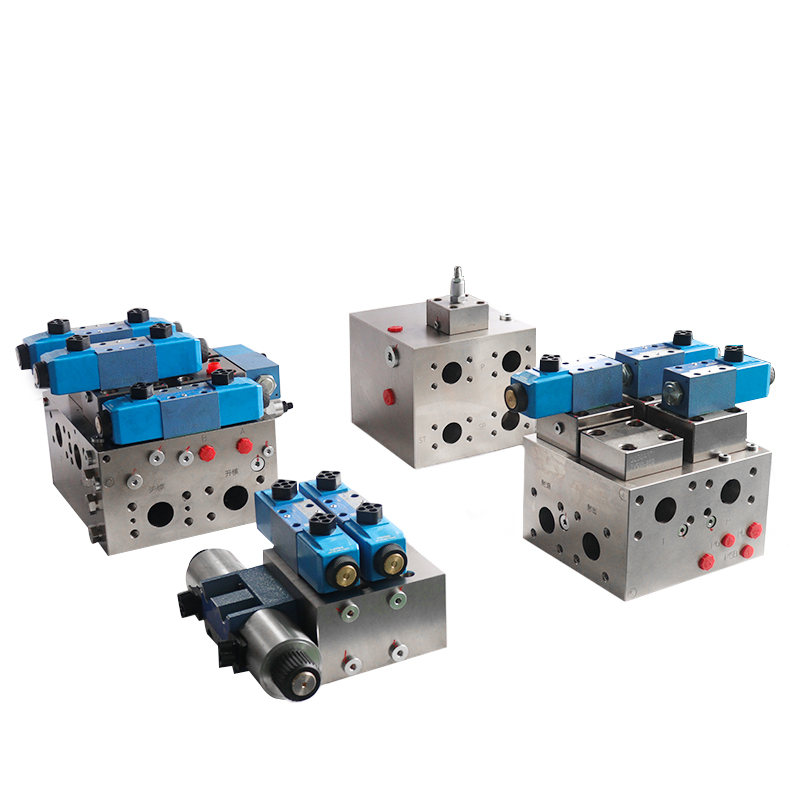
Proportional solenoid is undoubtedly one of the core devices of solenoid cartridge valve.
Based on the output characteristics, solenoid cartridge valve proportional solenoids are mainly classified into the three types in the table below.
| framework | Input/Output Characteristics | make use of | ||||
| 一 | Force-controlled | The structure is exactly the same, only differences in use | Current – output force | Proportional to the input current is the output force, which is independent of the armature displacement in the working area, i.e. it has horizontal suction characteristics. | Shorter stroke for pilot stage | |
| 二 | Stroke control type | Force control type + load spring | Current – Force – Displacement | Proportional to the input current is the output displacement converted by the load spring | Larger output stroke, mostly used for direct-controlled valves | |
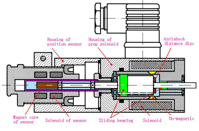
| 三 | Position-adjustable | Force control + displacement sensor | Added small closed loop for armature position | Current – armature position | With the input current is proportional to the armature displacement and has nothing to do with the counterforce, the size of the specific force within the maximum suction by the load needs to be set. | Closed loop with armature position feedback for direct control valves requiring high control accuracy |
However, the most basic and commonly used type is the force-controlled proportional solenoid. In this type, the output force in the working area is proportional to the current and independent of the displacement. This characteristic is precisely where the term “proportional” originates.
Therefore, unless otherwise specified, we refer to these as force-controlled proportional solenoids.
It is important to note that the proportional electromagnet is structurally similar to the switching electromagnet. The primary difference, however, lies in the shape of the core tube isolation ring. In ordinary switching solenoids, the pole shoe profile is generally rectangular.
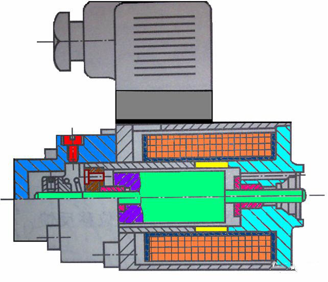
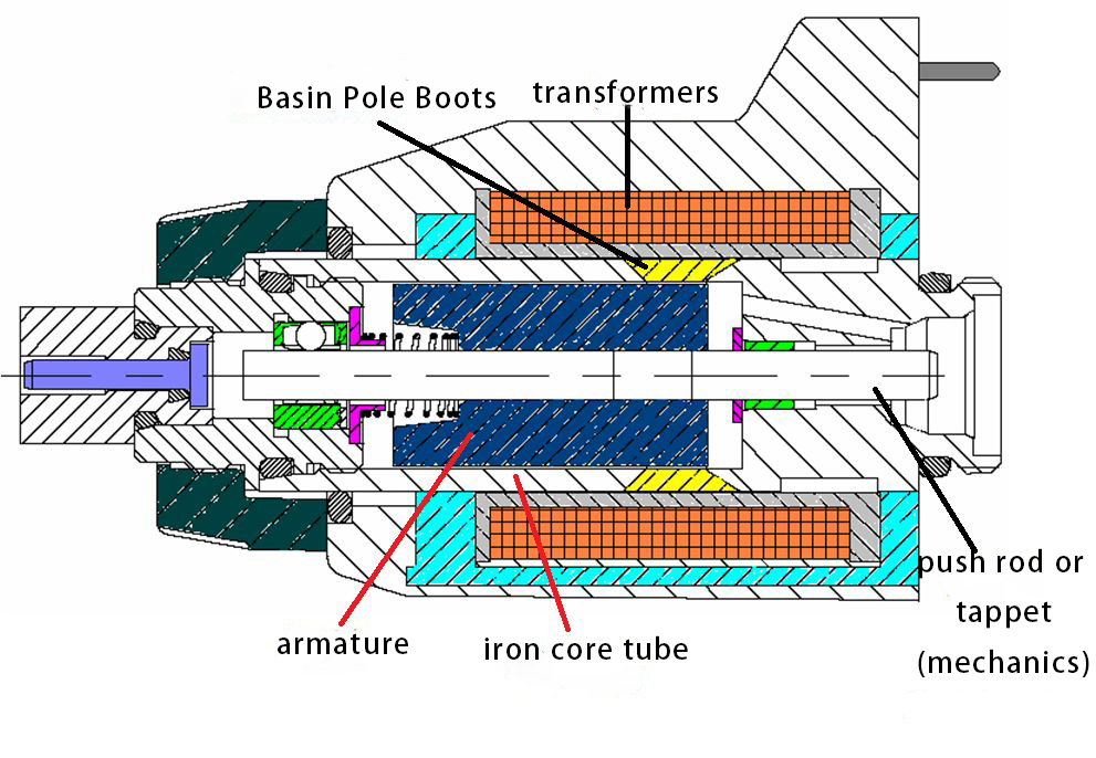
To illustrate, the principle of the proportional solenoid is shown in Figure 1 below. One of the key features here is the size of the pot-shaped pole shoe, which is highlighted in yellow.
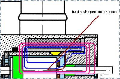
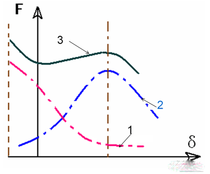
In contrast, Figure 4 represents the magnetic flux lines of the pole shoe in a switching electromagnet as a red line cluster. Consequently, the resulting travel force curve, shown as red line 1 in Figure 5, closely resembles that of the switching solenoid.
Following this, after converting the pole shoe to a basin type, some of the original magnetic flux lines transform into the blue lines depicted in Figure 4. As a result, the travel force curve now appears as blue curve 2 in Figure 5.
By adjusting the blue curve of the force-travel relationship and superimposing it with the red curve, we derive curve 3, which features a flat section as depicted in Figure 5.
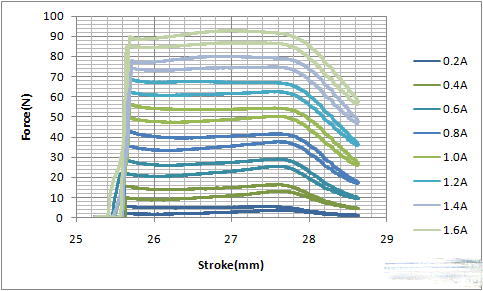
The characteristic of the flat segment of curve 3 signifies that the force remains constant while the stroke varies within this segment. The strength of the magnetic field determines the value of the force in the flat section. This magnetic field strength, in turn, depends on both the current and the number of turns in the coil.
For further clarity, Figure 6 displays the measured curves.
Contact Zhuo Yi Control Technology for the latest production technology!