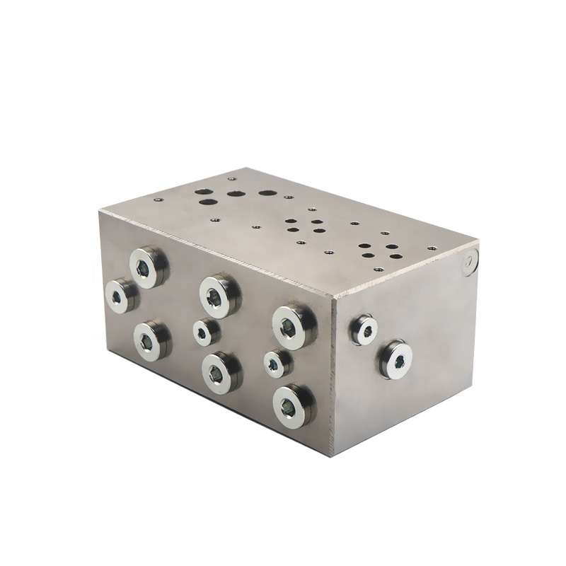
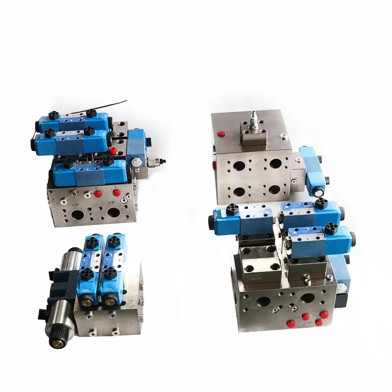
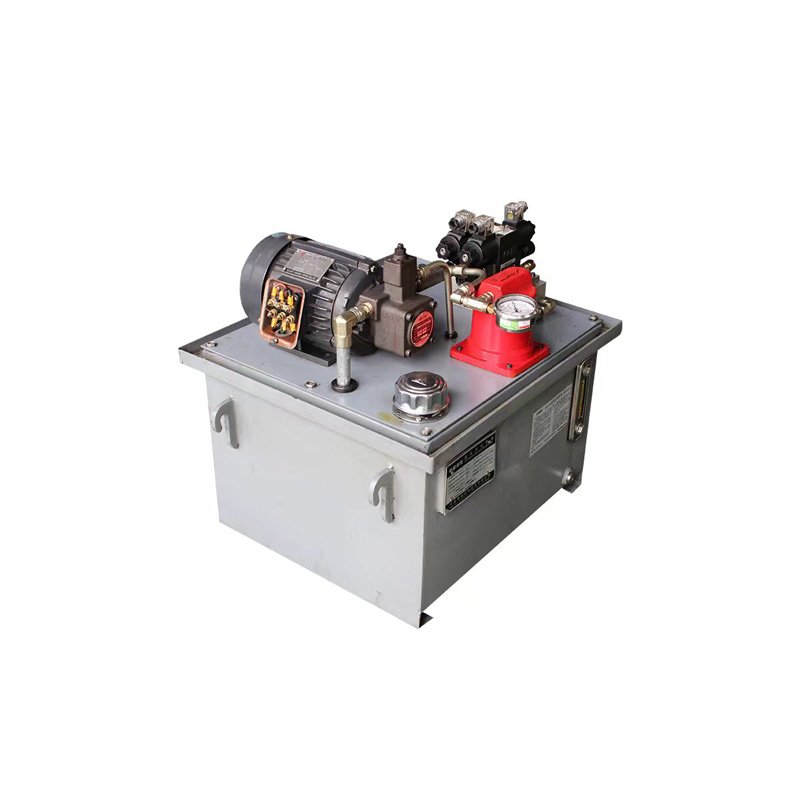
Figure 3-24 shows the production of hydraulic valves according to the hydraulic system circuit diagram of the hydraulic valve block. Hydraulic valve valve block is to make the connection between the valve oil circuit in the valve block entity in accordance with the requirements of the communication, the pathway connection is reliable, the volume can be the smallest. Its surface can be installed plate valve, two-way cartridge valves or threaded cartridge valves, there are also mounted cartridge valve cavity hole, connecting pipe fittings or flange of the oil port.

The hydraulic valve integrated block is shown in Figure 3-25a. For stacked valves, the valve itself acts as both an oil circuit block and a hydraulic valve. You can integrate several stacked valves to form a standard hydraulic control circuit, as shown in Figure 3-25b.

Using an oil circuit block instead of piping to connect components can significantly reduce the system assembly workload. It also decreases the chance of leakage, reduces the space occupied by the system, and shortens the response time of the actuator. Additionally, it lowers the cost of system maintenance. However, design and test the oil circuit block specifically for each application. If the integrated system has poor heat dissipation conditions, troubleshooting becomes more difficult. The factory must debug each unit individually to verify quality assurance.
Now most of the oil circuit block design using hydraulic valve block CAD special software, but also in AutoCAD on their own development. In this regard, you can refer to books on threaded cartridge valves, and many threaded cartridge valve companies have their own company-specific software, from the schematic design, selection, simulation and valve block generation to provide a package solution. Therefore, hydraulic cartridge valve block design efficiency can be improved a lot.
In the design should also pay attention to the hydraulic valve arrangement skills, should avoid the valve block is too large, too many elongated holes, to prevent increased costs, processing difficulties, burr cleaning difficulties. However, there is no uniform experience for scheduling the hydraulic valve block above the hydraulic valve arrangement. In general, pay attention to the six faces of the hydraulic valve: use one face as the fixed position, two faces for pipeline oil inlet and outlet, and leave three faces available for valve installation. Set up one of these faces for pressure gauges or sensors to facilitate observation and operation.
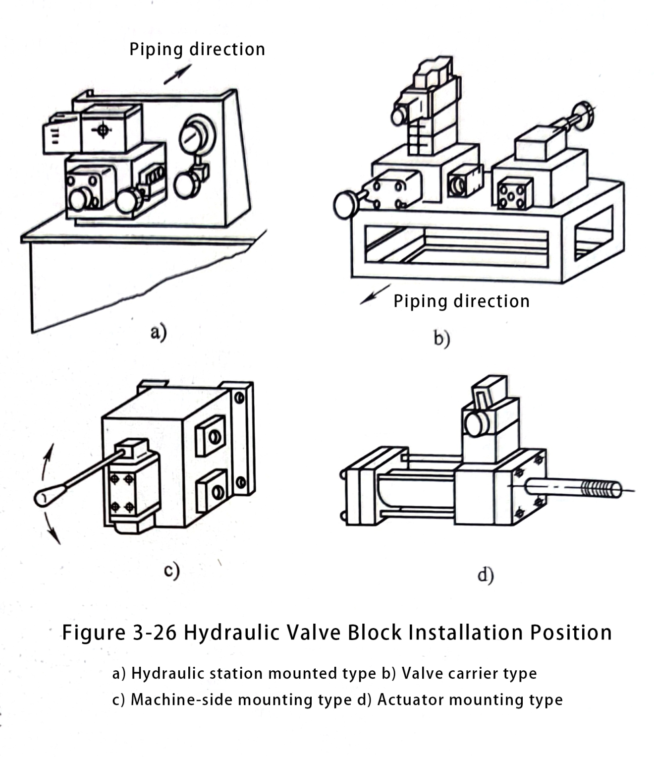
The system sets up the oil circuit block in four cases. These are: in the hydraulic station, in the independent valve frame, on the host body side, and directly on the actuator. This setup is illustrated in Figure 3-26. To determine the setting of the oil circuit block, first decide on the arrangement of the components within the block. Then consider the following factors: whether the oil circuit block will be horizontal or vertical. Also, decide whether it will be mounted on the panel or placed on the bench. Also, think about the direction of the piping, potential interference with other equipment, and the convenience for operation and maintenance. Additionally, assess the presence of idle volume and methods to reduce surface grinding and drilling processes.
Always consider pressure loss when determining the orifice diameter. Control the flow rate of the inlet channel to be between 3 and 6 m/s. Keep the flow rate of the return channel below 1 to 3 m/s. Maintain the flow rate of the suction channel below 1 m/s. Ensure that the local channel does not exceed 10 m/s.
The misunderstanding in the design is that designers often refer to the size of the orifice of the plate valve. In this case, the flow rate may be as high as 10 m/s or more. Therefore, you cannot determine the diameter of the orifices of the oil circuit block based on the size of the connection to the orifices of the hydraulic valve.
Another design problem is the minimum wall thickness between unconnected orifices and between the orifices and the surface of the block. Figure 3-27 illustrates this issue.
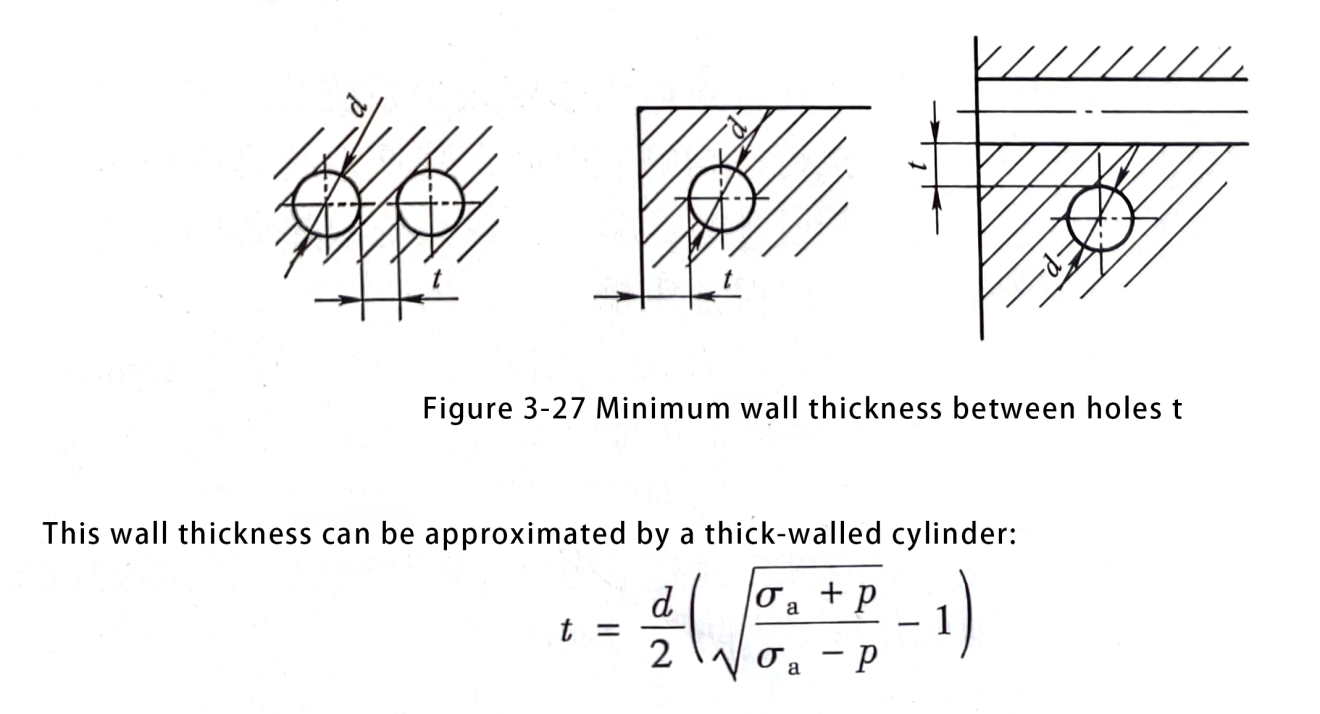
In actual design, consider a minimum wall thickness of more than 3 to 5 mm. This accounts for drawing errors, installation errors from drilling, runout and offset, and the tightening torque of pipe threads. The surface roughness of the valve or flange mounting surface Ra is not more than 0.8um. The surface roughness Ra of the mounting surface of the valve or flange and the bonding surface of the intermediate block is not more than 0.8 um. To prevent leakage, pay special attention to the perpendicularity between the center line of the oil port thread and the mounting surface of the seal. Accurately maintain this perpendicularity. Keep this perpendicularity precise.
Additionally, ensure that the oil circuit block bonding surface has no concave flatness defects. Also, lifting rings should be provided on large oil circuit blocks. Consider the convenience of drawing lines to reduce useless man-hours when determining the datum and marking the dimensions. Use axonometric diagrams on the construction drawings of the oil circuit block. These diagrams should show the communication relationship between the apertures schematically. The drawing of the oil circuit block should include the schematic diagram of the corresponding circuit. This diagram should show the oil circuit block equipped with the relevant components, as illustrated in Figure 3-24.
Contact Zhuo Yi Control Technology for the latest production technology!