
The power unit hydraulic pump is an important part of the hydraulic system assembly. The power output for the entire hydraulic system comes from the power unit hydraulic pump. Therefore, the reliability and stability of the power unit hydraulic pump design significantly impact the entire hydraulic system. A set of equipment for the hydraulic system often have the following requirements for the hydraulic station: oil pressure is stable, there can not be too big fluctuations; fluid temperature can not be too high; external power supply sudden power failure or system failure can give the cylinder and other power components to provide reliable protection. Therefore, a high reliability, good stability of the hydraulic station for the entire hydraulic system and equipment is essential for stable operation.
Based on the characteristics of the power unit hydraulic pump in this study, the following section describes the design of the hydraulic station from the principle of the power unit hydraulic pump.
Principle of power unit hydraulic pump
The power unit hydraulic pump is designed according to the principle of single fault protection. The design includes two sets of circuits. One of these circuits serves as a standby circuit. This setup ensures the normal supply of oil in the event of a failure of one of the circuits. Figure 1 shows the schematic diagram of the hydraulic station system.
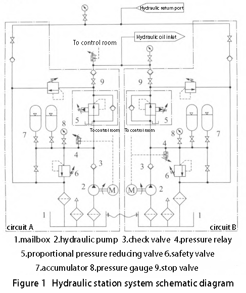
As shown in Figure 1, the power unit hydraulic pump has A, B two identical circuits, of which the B circuit is a standby circuit, only the A circuit operates during normal operation, and only when the A circuit fails, the B circuit starts to work. In normal operation, the motor starts to drive the hydraulic pump, which supplies oil and generates output pressure. Meanwhile, the accumulator fills with oil through the check valve. The system then regulates the pressure through the pressure reducing valve to achieve the exact pressure required.
When the hydraulic power components in the system stop working, the accumulator provides pressure protection for the entire circuit. This ensures that the system maintains a stable pressure. The pressure relay detects the accumulator pressure. When the accumulator pressure reaches the maximum set value, the motor stops rotating, and the hydraulic pump ceases to supply oil. If the pressure in the accumulator does not reach the maximum set value, the hydraulic pump will continue to fill the accumulator. The pump will keep filling the accumulator until it reaches the maximum set value for the accumulator pressure.
When the power unit hydraulic pump operates again, the fully pressurized accumulator first supplies oil to the system and outputs pressure. As the pressure in the accumulator decreases, the motor starts to refill the accumulator with oil. At the same time, the motor supplies oil to the system and maintains the output pressure. The accumulator can ensure that the system pressure stays within a certain range, maintaining the stability of the system pressure. After the fluid passes through the pressure reducing valve, the pressure pulsation of the fluid becomes smaller. This reduction in pulsation, combined with accurate pressure reduction, helps stabilize the pressure.
The switching between the two circuits A and B of the power unit hydraulic pump relies on the different set pressure values of the pressure reducing valves of the two circuits. The set pressure value of the circuit pressure reducing valve is higher than the pressure value of the B circuit. Therefore, when the A circuit is working, the B circuit will not supply oil at the oil supply port. This is because the pressure reducing valve of the B circuit has a lower pressure value than the oil supply pressure of the A circuit.
When the A circuit fails, the pressure value at the oil supply port decreases. If the pressure at the oil supply port drops below the set pressure value of the B circuit’s pressure reducing valve, the B circuit will start to work. The B circuit will supply oil because its pressure is higher than the oil supply port pressure after the pressure reducing valve. At this time, the pressure of the B circuit after the pressure reducing valve is greater than the pressure at the oil supply port. As a result, the B circuit starts to supply oil. This process realizes the automatic switching between the A and B circuits.
Structural design of power unit hydraulic pump
Power unit hydraulic pump structure layout
The overall arrangement of the power unit hydraulic pump is divided into centralised and decentralised, as shown in Figure 2, the structural layout of the power unit hydraulic pump form.
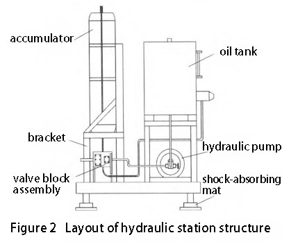
The design layout of the power unit hydraulic pump must ensure the hydraulic system functions effectively while minimizing vibration. This approach helps maintain the stability of the power unit hydraulic pump. Arranging the hydraulic station components in a scattered manner wastes resources and creates a messy situation with oil pipes and lines. This arrangement will also bring difficulties to maintenance. To reduce the impact of vibration on the hydraulic system, consider the following points. First, design the hydraulic station layout to balance aesthetics and maintenance convenience. Using an independent centralized arrangement proves to be more reasonable and effective for this purpose.
Main components of the power unit hydraulic pump
Hydraulic power unit
The hydraulic power source device provides power to the hydraulic unit pump. This device mainly consists of hydraulic pumps, accumulators, and a hydraulic tank. Hydraulic power source device is an important part of the hydraulic station, a lot of hydraulic system oil pressure is not stable, hydraulic station noise, faults, most of the reasons for this part of the design is not reasonable. The power unit of the hydraulic pump uses hydraulic pumps and accumulators together as a power output design. The hydraulic pump provides stored energy to the accumulator. The accumulator, in turn, uses this stored energy to ensure that the pump does not need to work constantly to maintain the system’s oil supply and pressure stability. Additionally, the accumulator plays a role in supplying oil in emergencies.
Hydraulic control unit
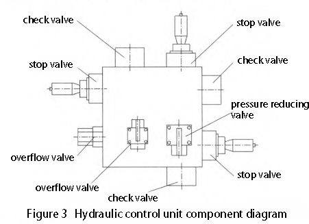
Hydraulic control device is a hydraulic system of various types of control valves and their connections: the collective name of the pieces, and the connection of various types of hydraulic components and pipe connection, plate connection and integrated connection of three kinds. The design integrates the hydraulic control device of the power unit hydraulic pump, with the valves combined into a single valve plate. The component diagram for the hydraulic control device is shown in Figure 3. This integrated hydraulic control device, there is no piping connection between the valves, increasing the space for valve installation and improving the overall reliability of the control device.
Safety protection measures for power unit hydraulic pump
The power unit hydraulic pump safety protection measures are set as follows.
Oil supply pressure monitoring and safety protection
We set up two independent pressure monitoring devices at different locations of the power unit hydraulic pump’s oil supply port. This setup ensures that if one pressure detection device fails, the other can continue to operate normally. We set up two independent, trigger-pressure-adjustable safety valves at the oil supply port. Both trigger pressures are set to the highest working pressure of the system. This ensures that even in the event of a pressure-reducing valve failure or hydraulic user equipment impact, the inlet pressure does not exceed the system’s highest working pressure.
When the system detects that the oil pressure at the oil supply port reaches the maximum detection pressure value, it will issue an alarm. At the same time, the motor of the working circuit will stop, causing the pressure at the oil supply port to decrease. The system will then automatically switch to the standby circuit. If leakage occurs in the pipeline or components of the hydraulic station, it will cause a decrease in the pressure at the oil supply port. The system will then detect that the oil pressure is lower than the set value. The system will then issue an alarm and automatically switch to the standby circuit.
If an accident causes this safety valve to supply oil abnormally at the oil supply port, you can manually close the terminal shut-off valve of this circuit. This action will disconnect the circuit. During maintenance, you can relieve the pressure in the supply port section by adjusting the trigger pressure of both safety valves.
Accumulator pressure monitoring
The accumulator part of each circuit is equipped with two pressure monitoring devices. One device provides an electrical signal that can be transmitted remotely. The other device offers a local display signal. You can observe this part of the monitoring signal locally. You can also transmit it remotely. This signal can be used as a control signal for the hydraulic pump motor. When the detected oil pressure value reaches the maximum pressure of the accumulator, the hydraulic pump stops working. When the detected oil pressure value falls below the maximum pressure of the accumulator, the hydraulic pump starts working again. The hydraulic pump supplies oil to both the accumulator and the system.
Accumulator overflow and pressure relief devices
An adjustable pressure relief valve is installed in the accumulator of each circuit. Under normal operating conditions, set the trigger pressure of this relief valve to the maximum working pressure of the accumulator. This ensures that the accumulator pressure does not exceed the maximum working pressure. It applies if an accident prevents the hydraulic pump motor from stopping. When a circuit failure occurs, adjust the circuit switching after the relief valve triggers to reduce the accumulator pressure to a minimum. Then, open the shut-off valve between the accumulator and the return filter to allow the accumulator to return oil to the tank, enabling inspection and repair of the accumulator.
Damping of power unit hydraulic pump
At the bottom of the power unit hydraulic pump bracket, there are four support legs. Install a shock-absorbing pad under each support leg. Fix the shock-absorbing pads to the ground with bolts. This setup reduces the impact of earthquakes or external vibrations on the hydraulic station. It ensures that the hydraulic station remains intact and stable in such situations.
This power unit hydraulic pump adopts the design of double pressure maintaining circuits. The two circuits switch automatically. This design greatly improves the stability and reliability of the hydraulic station. This pressure-maintaining circuit design ensures the stability of the system oil pressure. It also reduces the waste of energy in the hydraulic station. By using accumulators to maintain pressure, the design helps save energy. The design of the power unit hydraulic pump circuit includes safety measures. These measures monitor the hydraulic station during various accidents. They also issue alarms and provide protection. This ensures the safety and reliability of the entire system.
Contact Zhuo Yi Control Technology for the latest production technology!


