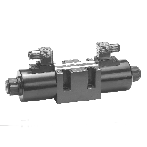
Recently, we have been sharing information related to the design of electric hydraulic valve block. Painting the electric hydraulic valve block inevitably involves addressing the oil port, so today we will focus on discussing the oil port in detail. We usually divide the oil port into threaded oil ports and flange oil ports. Let’s take a look at these.
Threaded oil ports
First of all, let’s look at the threaded port, in general, when the diameter of the hole is less than 25mm, we choose the threaded port.
The three most commonly used standards for threaded orifices are:
Metric thread, Thread angle 60 °, the thread characteristics of the code with M;
Inch thread, Thread angle 55 °, the thread characteristics of the code with G;
American Thread, Thread angle 60°, its thread characteristic code with UNF;
If you look directly at the object, as if all three look similar, you are really difficult to immediately distinguish them with the naked eye who is who. However, their thread, pitch, and diameter specifications differ, and they need to match specific threading tools for accurate measurement. Therefore, they cannot be interchangeable.
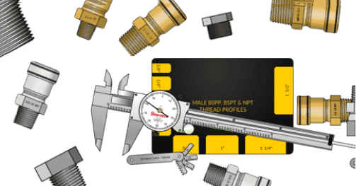
However, if the fittings are not universal and you force a fitting with mismatched threads into a threaded oil port, you might screw it in, but the results will not be favorable. The threads of both the fitting and the oil port are likely to get damaged.
| Classification of pipe threads | ||
| by system of units | by tooth type | by sealing |
| inch system | 55° pipe thread | 55° sealed pipe thread |
| 55° unsealed pipe thread | ||
| 60° pipe thread | 60° sealed pipe thread | |
| 60° unsealed pipe thread | ||
| metric system | metric 60° pipe thread | metric 60° sealed pipe thread |
| metric 60° unsealed pipe thread | ||
Naming rules for threads
What also gives designers a headache is that each standard has a different way of naming threads, and it’s easy to get sidetracked. Here’s a list:
Metric thread naming rules, with the thread diameter multiplied by the pitch, such as M20x1.5, where 20 indicates that the thread diameter is 20mm, 1.5 indicates that the pitch of the thread is 1.5mm;
The naming rules of the British system thread, with the nominal pipe diameter, such as G1/2‘, of which 1/2’ that the nominal pipe diameter of 1/2 inch, while the actual thread diameter is 20.64mm, that is to say, you can’t say that with 1/2×25.4 to directly calculate the diameter of the G1/2’ thread.
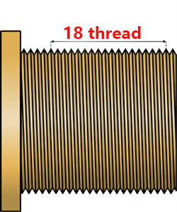
The naming rules for American threads use inches, but unlike British threads, they express the thread’s diameter in terms of the large diameter.For example, in 3/4‘-16UNF, the 3/4‘ indicates a thread diameter of 19.05 mm. We derive 19.05 mm from 3/4 x 25.4 (1 inch = 25.4 mm). The 16 indicates that 1 inch contains 16 threads.
Flange oil port
When the orifice diameter exceeds 25mm, opt for a flange oil port. Although large-sized threaded joints are available, they require a very large spanner for tightening and need considerable operating space. Since the purpose of using a electric hydraulic valve block is to save space, we switch to a flange connection. You only need to evenly distribute the bolts around the flange and tighten them to secure it. Well, of course, the seal between the two is to rely on the O-ring between the two bonding surface to achieve.
According to the standard, we can divide flange joints into three types: metric square flange, British diamond flange, and American SAE flange.
The American SAE flange with the same specification also divides into two types: the light series (3000 psi) and the heavy series (6000 psi). In addition, the 4 bolts used for fixing also divided into metric bolts and American bolts. These should not be confused.
We know that most of the hydraulic pump oil port for the flange oil port, here we look at a hydraulic pump oil port video, to deepen the understanding.
Why do so many thread sizes exist in the world?
Finally, let’s discuss an interesting topic: the variety of thread specifications. This issue has plagued many designers. Despite the existence of various international standards for so many years, why haven’t we unified them? In fact, it is not that they do not want to unify, but really can not do!
Imagine that you have gradually entered the era of Industry 4.0, then the world has already existed and will produce hundreds of millions of equipment. These devices are produced and manufactured in different countries, in different geographical areas. Each country has its own applicable standards, the existing relatively large standard system has metric standards, British standards, American standards, Japanese standards, French standards, Chinese national standards and so on. They can’t convince anyone to give up their own standards, which will suffer our group of mechanical practitioners.
Contact Zhuo Yi Control Technology for the latest production technology!