
Hydraulic cartridge valve is another type of hydraulic control valve. Its basic core element is a liquid-controlled, single control port mounted in the oil circuit in the main stage of the two-way liquid resistance unit (so also known as two-way cartridge valve). The hydraulic cartridge valves can form various control function units. These units can be composed of one or several insert elements for different combinations. Additionally, they include the corresponding pilot control stage. For example, direction control function unit, pressure control unit, flow control unit, compound control function unit.
Hydraulic cartridge valve has the following characteristics:Cartridge valves have small internal resistance, making them suitable for high-flow work. Most of the valve ports use taper sealing, resulting in minimal leakage. They are also suitable for emulsions and other low-viscosity working mediums. The structure of cartridge valves is simple and reliable, with a high degree of standardization. For large flow, high pressure, and more complex hydraulic systems, cartridge valves can significantly reduce size and weight. Its structure is shown below:

It consists of the insertion element, control cover plate, and channel block. The insertion element includes a spool, valve sleeve, spring, and seals. The control cover plate installs the corresponding pilot control level components according to the different control functions of the cartridge valve. The channel block embeds the insertion element and installs the control cover plate onto the basic valve body, while also connecting the main oil circuit and control oil circuit. Among them, A and B are the main oil way ports, and C is the control oil way port. the pressure and acting area of A, B and C ports are PA, PB, PC and A1, A2, A3, A3=A1+A2, and Fs is the spring force.
Figure 2 shows the hydraulic schematic diagram of the main cylinder part of the solid tyre curing unit hydraulic system (part of the system schematic diagram, not the complete schematic diagram).
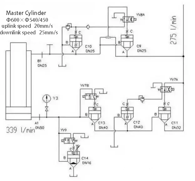
As shown in the figure, hydraulic cartridge valves control the entire system, performing the functions of various hydraulic valves. According to the characteristics of the machinery and the main technical parameters—cylinder upward speed of 20 mm/s, downward speed of 25 mm/s, cylinder diameter/rod diameter Φ600 mm/Φ540 mm—you can use the formula flow Q = A * V to determine that the cylinder’s oil chamber requires a flow of 339 L/min. The required flow rate is larger. We considered the sensitivity requirements for mechanical movement and the stricter sealing requirements of the hydraulic system. Based on these factors, we chose cartridge valves as the control element for the oil line. The host system demands high sensitivity for mechanical movement and stricter sealing requirements for the hydraulic system. After comprehensive consideration, we chose the cartridge valve as the control element for the oil circuit.
Two way cartridge valves form a variety of combination valves
Hydraulic cartridge valve constitutes pressure control valve
According to the working principle of cartridge valve, when PAA1+PBA2>PCA3+FS, the spool opens and the oil circuit A and B are connected. As shown in Figure 2, when solenoid valve YV9 powers the hydraulic cartridge valve C14, the system connects port C of C14 directly to the tank. This connection results in zero pressure at port C. When observing the system, you can see that when oil lines A and B connect, and the pressure at port A exceeds the spring force, the system pressure oil returns to the tank. In this scenario, the hydraulic cartridge valve acts as a relief valve, controlling the pressure at the cylinder’s diameter port.
Look at the following example of a Figure 3 cartridge valve as a relief valve.
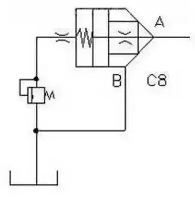
The hydraulic cartridge valve C8 connects port B directly to the tank and port C to the relief valve, both having zero pressure. When the pressure at port A exceeds the spring force, ports A and B connect. This connection allows the oil pressure to flow through port B back to the tank. At this moment, the cartridge valve acts as a relief valve, controlling the system pressure.
Hydraulic cartridge valve constitutes directional control
Look at Figure 2, the hydraulic action procedure table shows that solenoid valves YV7A and YV7B control the main cylinder’s upward movement simultaneously. When both cartridge valves C11 and C13 are active simultaneously, port C of each valve connects through the tank. If PA > FS, ports A and B connect directly, allowing oil to flow from port A to port B. When only YV7B is powered, the main cylinder moves downward. C13 PA <PB, spool open, oil can flow from B to A. This two, cartridge valve plays the role of check valve.
Look at the other diagram, Figure 4 2-position 3-way valve.
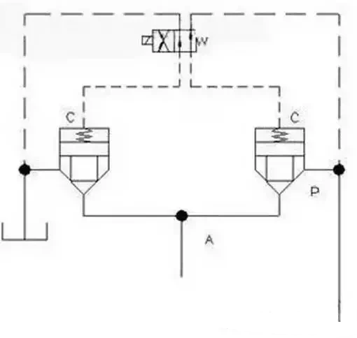
This hydraulic cartridge valve is a two-position two-way valve. When the two-position three-way solenoid valve is de-energized, the spool opens, connecting A and B. When you energize the solenoid valve, it closes the spool and prevents A and B from connecting.
Hydraulic cartridge valve constitutes flow control valve
As shown in Figure 2, C14 has a spool lifting limit device on the valve’s top cover. By adjusting the position of this limit device, you can change the size of the valve port cross-section to regulate the flow rate. By adjusting the position of the restriction device, you can change the size of the valve port flow section, thus regulating the flow rate. This cartridge valve is used as a throttle valve.
Summary
By using more complex combinations, you can realize more functions of hydraulic valves. By combining hydraulic cartridge valves, you can use them as pressure control valves, such as sequence valves and pressure reducing valves. They can also serve as flow control valves, including one-way throttle valves and throttle valves. Additionally, they function as directional control valves, such as speed regulating valves, pilot-operated check valves, and two-position, two-way directional valves. Furthermore, you can use them as compound valves.
Currently, there are several series of hydraulic cartridge valves as follows: K series cartridge valves, L series cartridge valves, TJ series cartridge valves, Z series cartridge valves. Several series models are different, and manufacturers can design and manufacture integrated channel blocks according to user requirements. Hydraulic systems widely use cartridge valves according to their characteristics.
Contact Zhuo Yi Control Technology for the latest production technology!


