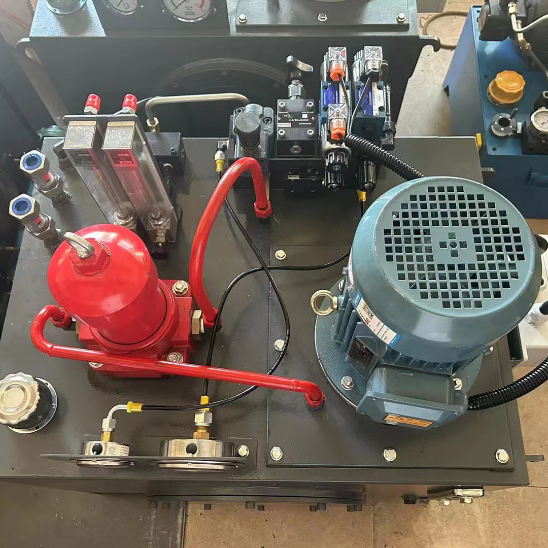
The hydraulic power pack units hydraulic system uses oil as the working medium. It utilizes oil pressure energy and, through control valves and other accessories, manipulates the hydraulic actuator’s work. This entire set of devices can produce a lot of force and is easy to control. You can easily obtain hydraulic oil with very high pressure (20-30MPa) using hydraulic pumps, and this pressurized oil can produce a lot of force when it enters the hydraulic cylinder.
For example, a hydraulic cylinder with a diameter of 30 cm and a pressure of 20 MPa can generate a force of up to 1413 kN. Thus, you can widely use hydraulic technology in presses, machine tools, automobiles, and other machines. Overload can be easily prevented in hydraulic systems of hydraulic power pack units by using safety valves (relief valves). This ensures safety even in situations where unanticipated load variations may occur, such as in construction machinery. Of course, you can choose the installation position freely for a hydraulic station’s hydraulic system, which is compact in size but has a large output. You can place the control valves and actuators in various locations. Simply connect the pipe or hose to complete the setup, providing significant freedom in the design.
Design requirements and technical parameters of the hydraulic system of the hydraulic power pack units
1、 First of all, to determine the use of hydraulic systems hydraulic station host, process, structural layout, conditions of use, performance, working environment and other circumstances.
2、 the host of the hydraulic system hydraulic power pack units work performance, such as speed range, smoothness of movement, conversion accuracy, transmission efficiency, control mode, signal source, automation and other requirements.
3、 To use hydraulic transmission in hydraulic power pack units, you need to clear the hydraulic system. Understand the action cycle and the working body cycle. Analyze the movement chain between the institutions. Ensure that all components comply with safety requirements.
4、 To understand the movement characteristics of the hydraulic drive mechanism, determine the form of movement in the hydraulic power pack units. Identify whether the movement is linear, rotary, or swinging. Also, assess the parameters such as displacement, speed, acceleration, and their size and range.
5、 The nature and size of the working load of the hydraulic drive mechanism, the hydraulic system is resistance load or beyond the load, constant value load, variable value load, and the size of each load.
6、 Hydraulic system hydraulic station prime mover type is how, is an electric motor or internal combustion engine. The efficiency, speed and torque characteristics of the hydraulic power pack units prime mover.
7、 The hydraulic system hydraulic station of the constraints of the problem, such as dust, explosion-proof, cold, pressure pulsation, shock, vibration noise and safety and reliability requirements.
8、 The last consideration is the economic requirements of the hydraulic station. You need to evaluate the cost of operating the hydraulic station, including energy consumption and maintenance. Additionally, consider the warranty period and overhaul conditions.

Hydraulic power pack units hydraulic system can achieve what function
1、It can automatically realise overload protection.
2、It is easy to realise linear motion.
3、 Light weight, small size, small movement inertia, fast response speed.
4、 Easy to manipulate and control, can achieve a wide range of stepless speed regulation.
5、 Hydraulic transmission of various components, according to the need for convenient and flexible to layout.
6、 Generally using mineral oil as a working medium, relative movement surface can be self-lubricating, long service life;
7、 You can easily achieve machine automation by adopting electro-hydraulic joint control. This approach not only allows for a higher degree of automatic control but also enables remote control.

Hydraulic power pack units hydraulic system piping how to pay attention to piping?
The location of the hydraulic system piping installation, the total length of the piping, the top and bottom, left and right curvatures, and the fittings, etc., are things to keep in mind when piping:
1、 When you install piping on the equipment, arrange it in parallel or vertical directions. Pay attention to neatness and minimize the crossing of pipes.
2、 Keep the entire pipeline as short as possible, minimize the number of turns, ensure smooth transitions, and reduce the number of up and down bends and joints. This will help accommodate pipeline expansion and deformation. At locations with live joints, ensure that the pipeline length allows for easy dismantling and installation of the live joints. Design the system so that you can freely dismantle the main pipeline or auxiliary components without affecting the other components.
3、 Pipes cannot be joined in the rounded part, but must be joined in the flat and straight part. When the flange is welded, it should be at right angles to the centre line of the pipeline. When you install flanges on pipelines with bends, install them only on the straight sections of the pipelines.
4、 There should be a discretionary gap of 10mm or more between parallel or intersecting pipelines to prevent interference and vibration.
5、The connection of pipeline has three kinds: threaded connection, flange connection and welding. Can be selected according to the pressure, pipe diameter and material. Threaded connection is suitable for smaller diameter oil pipe, low-pressure pipe in 2in (lin-25.4mm) below, high-pressure pipe in lin below. When the pipe diameter is larger, flange connection is used. Welding connection has a low cost and is not easy to leak. To ensure good installation and dismantling conditions, try to use butt welding. This approach helps to reduce the number of pipe fittings and prevents air from being released from the pipeline during movement.
6、 Equip the highest part of the pipeline with an exhaust device to bleed off the air when you start the system.
7、 All pipelines should be installed in two decisions. During the first trial installation, weld the pipe joints and flanges in the appropriate positions. Once you determine the entire pipeline layout, remove it for pickling or cleaning, then dry it, oil it, and test the pressure. Ensure that sand, iron oxide, iron filings, and other dirt do not enter the pipeline and components during the final installation.

Hydraulic system hydraulic power pack units piping graphic symbols
1、Piping diagram symbols
Indicate the category code of other media in the pipeline using the first capital letter of the English name of the phase. Alternatively, use the first two capital letters if the category code repeats, as shown in the following table. You can also use the medium’s compound molecular formula (such as H₂SO₄ for sulfuric acid) or the international common code (such as PVC for polyvinyl chloride) to specify its category.
2、 If necessary, you can note Arabic numerals in the lower right corner of the category code to distinguish between different states and types of media.
How the hydraulic system of the hydraulic power pack units is unpressurised
1. Inspection and installation
When you disassemble all hydraulic components, carefully inspect them. Determine which parts you can continue to use. Identify which parts you can still use after repair. Also, identify which parts you need to replace immediately. After determining that there is no error, the parts can be used for each carefully cleaned. Only then can it be assembled in a specific order. After completing the assembly, you should not immediately put the system into use. Instead, perform several reciprocating motions under low pressure to eliminate the cylinder gas.
2. Cut off the power or power source
The most important step of the hydraulic system pressure relief is to cut off the power supply or power source, so that the hydraulic device all stop running. When the system is static, you can perform some preliminary work to remove pressure. For example, before dismantling hydraulic cylinders, you should depressurize the hydraulic circuit.
3. Disassembly in order
When the hydraulic power pack units of the hydraulic system are completely static, you can disassemble them after completing the preliminary work to relieve the pressure. When disassembling the hydraulic system hydraulic station, it is important to do it in order. However, due to the structure and size of the hydraulic system is not the same, its order is slightly different. Of course, during the entire disassembly process, you must take measures to prevent surrounding dust and impurities from contaminating the parts of the hydraulic system.
How to solve the hydraulic power pack units hydraulic system oil temperature is too high
A higher oil temperature in hydraulic power pack units is one of the main reasons affecting the reliability of the system and its components. It also impacts the efficiency of the entire machine operation. How to ensure that the loader hydraulic system in the use of oil temperature in the normal state, is to ensure that the machine normal and reliable operation of the key. The relief valve in the system causes the largest power loss. The gravity of the bucket, heavy block, and moving arm generates heat in the hydraulic system. Additionally, the power loss from the pipeline and local pressure also contributes to heating the hydraulic system. Addressing the issue of excessive temperature in the loader’s hydraulic system is crucial.
1、 A reasonable layout of the hydraulic pipeline should use limited space efficiently and reduce the length of the pipeline. Avoid unnecessary pipe bending and throttling whenever possible. Minimize sudden changes in diameter and reduce the number of pipe joints. These measures help to decrease local pressure loss caused by changes in flow and flow rate.
2、 To regularly replace the hydraulic station oil temperature fluid; regularly check the suction and return, whether the oil filter is clogged.
3、 If the surrounding environment is too high will also make the hydraulic station oil temperature temperature rise, at this time the main measures to take the following:
a. Increase the flow rate of the air on the surface of the heat sink, so that the heat dissipation coefficient of the surface of the heat sink increases, thus improving the heat dissipation capacity.
b. If there is a water cooler, you can increase the flow of water to remove more heat. If necessary, you can also add a water pump to force an increase in the water flow. This will help to reduce the oil temperature of the hydraulic station.
4、 In the system work, the excess oil to avoid or reduce as much as possible from the relief valve overflow back to the tank, at this time can take the following measures:
a. Excess oil is automatically unloaded at low pressure, the high pressure oil is unloaded back to the tank at low pressure.
b. Install an automatic limit block on the loader’s working device. This block will signal the opening of the relief valve before it opens. By doing this, you will artificially reduce the relief valve’s relief time.
c. Supply different oil volume with compound pump:
d. supplying the corresponding oil volume with a variable pump.
e. Store the excess oil with an accumulator.
5、 A reasonable choice of control valves: hydraulic power pack units oil temperature through the valve body pressure loss is much greater than the pressure loss in the pipeline. Complex internal structure of the valve body. Hydraulic station oil temperature through the valve body has a large local pressure loss. Generate a large amount of heat. Therefore, to meet the conditions of the loader, you should select a control valve with a small pressure loss whenever possible.
Hydraulic station hydraulic power pack units pollution and maintenance
First, the quality of the hydraulic system depends on the rationality of the system design and the performance of its components. It also depends on the system’s pollution protection and treatment. Pollution in the system has a direct impact on the reliability of the hydraulic system and the service life of its components. According to statistics, domestic and foreign hydraulic system failure about 70% is caused by pollution. Fluid pollution of the hydraulic system is mainly harmful as follows:
1、 Pollution causes wear on components. Fluid contaminants lead to various forms of wear and tear on the components. Solid particles can enter the gaps between moving parts, resulting in cutting wear or fatigue wear on the surface of the parts. High-speed liquid flow of solid particles on the surface of the component impact caused by erosion wear. Water in the fluid and the oxidative deterioration of the fluid generates corrosive effects on the components. In addition, air in the system fluid causes cavitation, resulting in component surface corrosion and damage.
2、 Solid particles can clog the gaps and orifices of the hydraulic valve. This clogging causes the spool to block and clamp. As a result, it affects the work performance and can even lead to serious accidents.
3、 Accelerating the deterioration of fluid performance occurs as water and air in the fluid, along with thermal energy, create the main conditions for fluid oxidation. Metal particles in the fluid act as a significant catalyst for this oxidation. Additionally, water and suspended bubbles in the fluid significantly reduce the strength of the oil film between moving parts, leading to decreased lubrication performance.
Contact Zhuo Yi Control Technology for the latest production technology!