
Hydraulic cartridge check valve, also known as logic valve, is a new type of hydraulic components, which is characterised by large flow capacity, good sealing performance, sensitive action, simple structure, and thus mainly used for larger flow rate of the hydraulic system or the sealing performance of the system requires high.
1. Hydraulic cartridge check valve structure principle and symbols
As shown in Figure 1, the valve assembly comprises several components: a control cover 1, a cartridge unit (which includes the valve sleeve 2, spring 3, spool 4, and seals), a cartridge block body 5, and a pilot element (which is placed on the control cover but not shown in the figure). This valve cartridge unit primarily manages the on and off functions within the circuit. Consequently, we also refer to it as a two-way cartridge valve.
The control cover plate encases the cartridge unit within the cartridge block body and facilitates communication between the pilot valve and the cartridge unit (also known as the main valve). The spool of the main valve regulates the on-off status of the main oil circuit. Depending on the type of pilot valve used, the system can achieve various functions such as pressure control, directional control, or flow control, and can even form composite controls.
Moreover, you can assemble multiple two-way cartridge valves with different control functions in one or more cartridge blocks to create a comprehensive hydraulic circuit. This approach allows for versatile and efficient hydraulic system design.
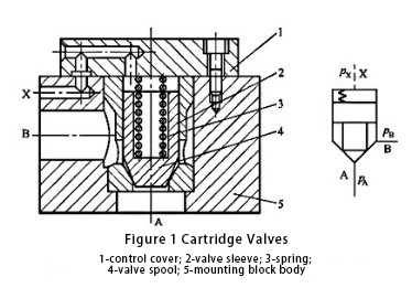
In terms of working principle, the two-way cartridge valve is equivalent to a pilot-controlled check valve. Specifically, A and B act as the only two working ports of the main oil circuit, and we commonly refer to this setup as a two-way valve. X acts as the control port. By altering the pressure at the control port, you can control whether the A and B ports are open or closed.
When the control port does not have hydraulic pressure, the liquid pressure acting on the lower part of the spool overcomes the spring force, causing the spool to open. This allows fluid to pass between A and B, with the direction of flow depending on the pressure at the A and B ports. Conversely, if the control port has hydraulic pressure, and when \( p_x \geq p_A \) and \( p_x \geq p_B \), the valve ensures that A and B remain closed. Consequently, it functions similarly to a ‘non-‘ gate in logic elements, and thus, people also refer to it as a logic valve.
Furthermore, we can divide cartridge valves into two categories based on the source of the control oil. The first category is external control cartridge valves. In these valves, a separate power source supplies the control oil, and the pressure at the A and B ports or the direction of control in the oil circuit does not influence this pressure.
On the other hand, the second category is internal control cartridge valves. In these valves, the system directs the control oil to the white valve of the A or B ports. Within this category, we further distinguish between two types: spools with damping holes and spools without damping holes. Notably, internal control cartridge valves are more widely used due to their versatile applications.
2. Directionally controlled cartridge valves
There are two kinds of check valves and directional valves.
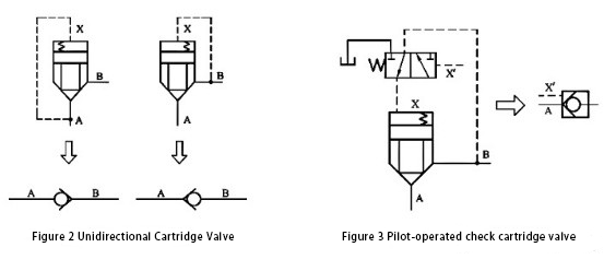
(1) One-way cartridge valve. As shown in Figure 2, we connect the X port to A or B, creating a one-way valve. Connecting method is different, its conduction direction is also different. The former pA> pB, cone valve closed, A and B can not be; pB> pA and reached the opening pressure, cone valve open, oil from B to A. The latter can be similar to analyse the conclusion.
(2) Pilot-controlled one-way cartridge valve. If you connect a two-position three-way hydraulic directional valve to the control cover to change the pressure at the X port, it becomes a liquid-controlled check valve, as shown in Figure 3. If there is no hydraulic pressure at X, the valve is in the position shown in the figure. When ( p_A > p_B ), A and B are connected, and A flows to B. However, when ( p_B > p_A ), A and B do not connect. If there is hydraulic pressure at K`, the two-position three-way pilot valve will be reversed. In this position, the X port is connected to the oil tank, and A and B are connected. The flow of oil depends on the pressure at the A and B points.
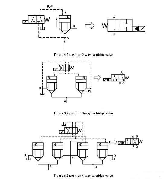
(3) Two-position two-way cartridge valve. As shown in Figure 4, the cone valve is open in the depicted state, connecting A and B. If the electromagnetic directional valve energised commutation, and pA>pB, the cone valve closed, A, B oil cut off, that is, two two-way valve.
(4) Two-position three-way cartridge valve. As shown in Figure 5, in the illustrated state, the left side of the cone valve is open, the right side of the cone valve is closed, i.e., A, O is connected, P, A does not pass. When you energize the solenoid valve, it connects P to A and keeps A from connecting to O. This setup functions as a two-position three-way valve.
(5) Two-position four-way cartridge valve. As shown in Figure 6, the left 1 and right 2 cone valves open in the illustrated state. This configuration achieves a connection between A and O, and between B and P. When you energize the solenoid valve, it opens the left 2 and right 1 cone valves. This configuration connects A to P and B to O. It functions as a two-position four-way valve.
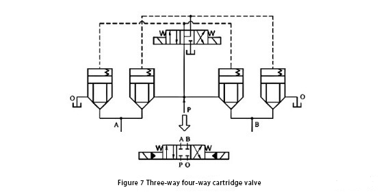
 (6) Three-position four-way cartridge valve. As shown in Fig. In the illustrated state of Figure 7, we close all four cone valves, so A, B, P, and O do not connect. When you energize the left solenoid, it opens the left 2 and right 1 cone valves. This configuration connects A to P and B to O. When the right solenoid energizes, it opens the left 1 and right 2 cone valves. As a result, it connects A to O and B to P. This configuration functions as a three-position four-way valve. If you use more than one pilot valve along with multiple main valves, you can create a complex system. You can combine this system into a two-way cartridge directional valve. This setup provides functionalities that ordinary directional valves cannot achieve.
3. Pressure control cartridge valves
In the cartridge valve control port with different pilot pressure valve, you can get a variety of different types of pressure control valve. Figure 8 (a) shows a direct-acting relief valve used as a pilot valve. This setup controls the main valve and we depict it in the relief valve schematic diagram. A cavity pressure oil through the damping hole into the control cavity and pilot valve, and the B port and the tank. By using the pilot valve, you can adjust the opening pressure of the cone valve. The principle is the same as that of a pilot-operated relief valve. If in Fig. 8 (a), when the B chamber is not connected to the tank but to the load, it is a sequence valve. In Fig. In Figure 8 (b), if you energize the 2-position 2-way solenoid-operated directional valve, you use it as an unloading valve.
Figure 8 (c) shows the schematic diagram of the pressure reducing valve. The main spool uses a normally open slide valve spool. B is the inlet, and A is the outlet. The pressure in cavity A passes through the damping holes and through the control cavity and the pilot valve. The operating principle is the same as that of the ordinary pilot diagram. Refer to Figure 8 for the pressure control cartridge type pressure reducing valve.
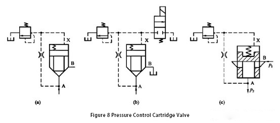
You can create a two-way cartridge electro-hydraulic relief valve by using a proportional relief valve as a pilot valve. This is an alternative to using the direct-acting relief valve shown in the figure.
4. Flow control cartridge valve
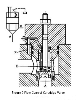
As shown in Figure 9, the cartridge valve control cover includes a spool travel regulator. This regulator adjusts the spool opening. By adjusting the spool opening, you enable the cone valve to function as a flow control valve. Furthermore, if you connect a constant differential pressure reducing valve in series with the two-way cartridge throttle valve, you will create a two-way cartridge speed control valve. Additionally, if you replace the throttle valve hand-adjustment device with a proportional solenoid, you can then utilize a two-way cartridge electro-hydraulic proportional throttle valve.
Contact Zhuo Yi Control Technology for the latest production technology!


