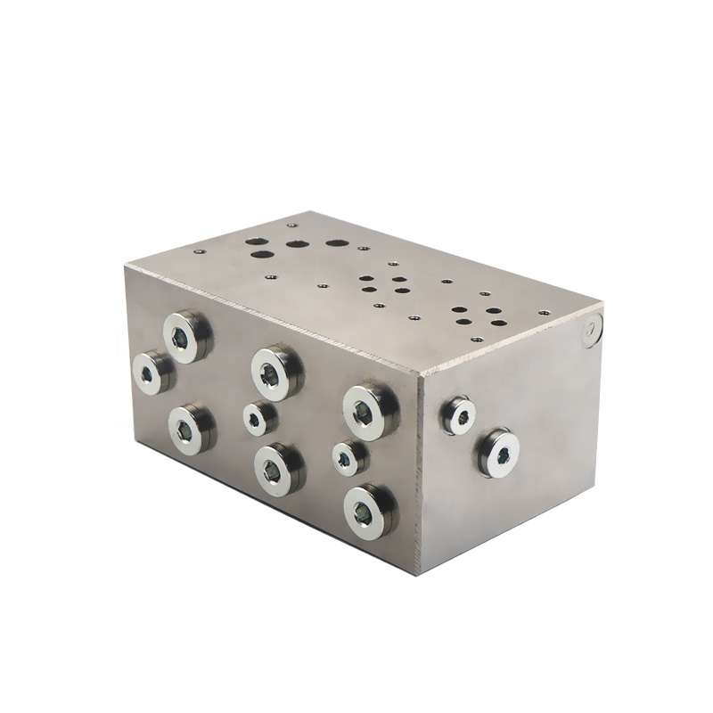
Overview
High pressure manifold blocks in the hydraulic system has been the importance of more and more people know, its application range is also more and more extensive. The use of high-pressure manifold blocks can simplify the design and installation of hydraulic systems. Additionally, it facilitates the integration and standardization of the hydraulic system. This approach helps reduce manufacturing costs and improve both precision and reliability. However, with the increase in the complexity of the hydraulic system, it also increases the difficulty of designing, manufacturing and debugging the high pressure manifold blocks. If you do not consider the design well, you will encounter a series of problems. These issues include a complicated manufacturing process, higher processing costs, raw material waste, and cumbersome use and maintenance.
Design of high pressure manifold blocks
Design Principles
The conformity of the high pressure manifold blocks’ oil circuit to the hydraulic system schematic is the first principle of the design. Before designing the valve block, first determine which part of the oil circuit can be integrated. The number of components included in each block should be moderate, too many components of the valve block volume, design, processing difficulties; components are too few, integration is not significant, resulting in material waste. For example, in the JISCO first steelmaking plant’s billet continuous casting machine shear hydraulic system, the hydraulic system uses cartridge valves to control the flow. This system requires high precision in action, and it places high demands on the reliability of system operation. Billet shear machine hydraulic system net block principle shown in Figure 1.
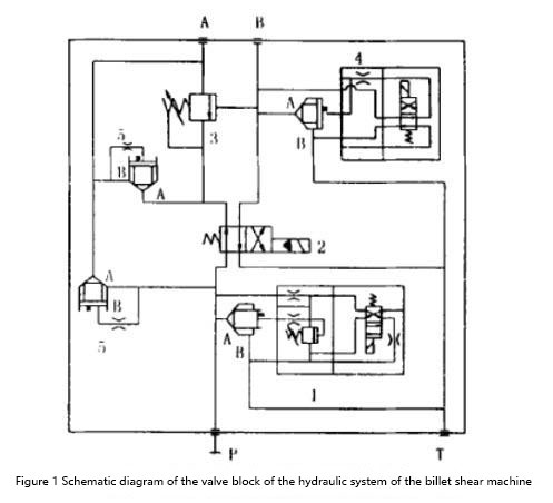
1、 relief valve: in order to protect the motor starting or stopping the pump in the low-pressure area to complete, so choose electromagnetic relief valve, and to ensure that high pressure and large flow of work demand, choose the relief valve with cartridge.
2、 the reversing valve: its role is to ensure that the hydraulic shear cylinder reversing smooth, no impact, and to ensure that only in the need to cut only when allowed to work, so as to avoid malfunction.
3、 counterbalance valve: the role of this network is to achieve the differential circuit for the panning control, used for hydraulic shear to carry out the fixed-foot cutting when the cylinder differential, in the billet shear when the valve action.
4、 unloading valve: in order to ensure that the hydraulic shear fast return, in the bypass at the addition of a normally closed valve, this valve only in the hydraulic shear return to work.
5、 cartridge valves: cartridge valves are selected as differential control.
In the design of the valve block, the oil circuit should be as simple as possible, to minimise deep holes, slant holes and process holes. To match the aperture and flow in the valve block, ensure that the hole provides enough through-flow area. Pay special attention to the direction and location of the inlet and outlet, and align them with the overall system layout and pipeline connection form. Additionally, consider the installation and operational requirements, including whether components need vertical or horizontal installation. Ensure that the installation meets these requirements. When designing adjustable components, consider the convenience of operation and observation. For example, position the adjustment handles of relief valves, speed control valves, and other adjustable components to facilitate easy operation. Need frequent maintenance components and key components such as proportional valves, servo valves, etc. should be in the valve block above or outside, so as to facilitate disassembly.
In addition, the design of the valve block to set up a sufficient number of pressure measurement points for the debugging of the valve block. For the weight of more than 30kg valve block. Should be set up to start the product screw holes. However, under the premise of meeting the requirements of use, the volume of the valve block should be as small as possible.
Dimensioning
When you design the valve block, ensure that a set of valve dimensions is self-contained. Mark the location of the reference screw holes on its mounting surface, and use the Kihuai screw holes as the standard for the rest of the relevant dimensions. Additionally, mark the oil port code of the installed components on the view. Include the size and depth of the oil port to facilitate processing and calibration of the orifice. Design the valve block assembly diagram to ensure that the installed components, fittings, and seals do not interfere with each other. The external dimensions should be marked on the assembly drawing.
Orifice arrangement
In arranging the valve block orifices, first determine the orientation of the oil ports according to the overall system arrangement. Place communicating ports as perpendicular to each other as possible on adjacent surfaces to simplify the orifice arrangement. Begin with the main oil circuit, then complete the small diameter oil circuits and control oil circuits. When you use deep hole runners, consider the length-to-diameter ratio and the possibility of drilling deflection.
Generally, keep the length-to-diameter ratio less than 10mm. Determine all hole spacing to ensure sufficient wall thickness strength. For medium and high-pressure systems using cast iron blocks, make the wall thickness greater than 5mm. For steel blocks, make the wall thickness greater than or equal to 3mm. If you drill a deep hole, you should also consider the allowable range of bit deflection and increase the hole spacing appropriately. The hole spacing should be increased appropriately. In addition, should also check whether the component mounting screw holes and other holes through.
Machining precision
The surface roughness of the mounting valve and flange on the high pressure manifold blocks should reach Ra0.4, and the surface roughness of the sealing surface of the end pipe joint should reach Ra3.2. In addition, the perpendicularity tolerance between the screw holes of the mounting pipe joint and its outer fitting surface should be at least 8 levels. You should meet the machining accuracy requirements for all screw holes on the net block, generally choosing 7H. Design the machining accuracy of threaded cartridge valve mounting holes according to the product sample requirements. The roughness of the mounting holes for cartridges should be Ra0.8. Additionally, there should be size tolerance and form tolerance requirements. The surface roughness of the O-ring groove should be Ra3.2. For general flow channels, the surface roughness should be Ra12.5.
Material Selection
High-pressure manifold blocks should preferably use 35# forged steel. For general valve blocks, A3 steel is suitable. When using gas cutting from plate block material, leave enough machining allowance. It is best to forge the block blank before processing.
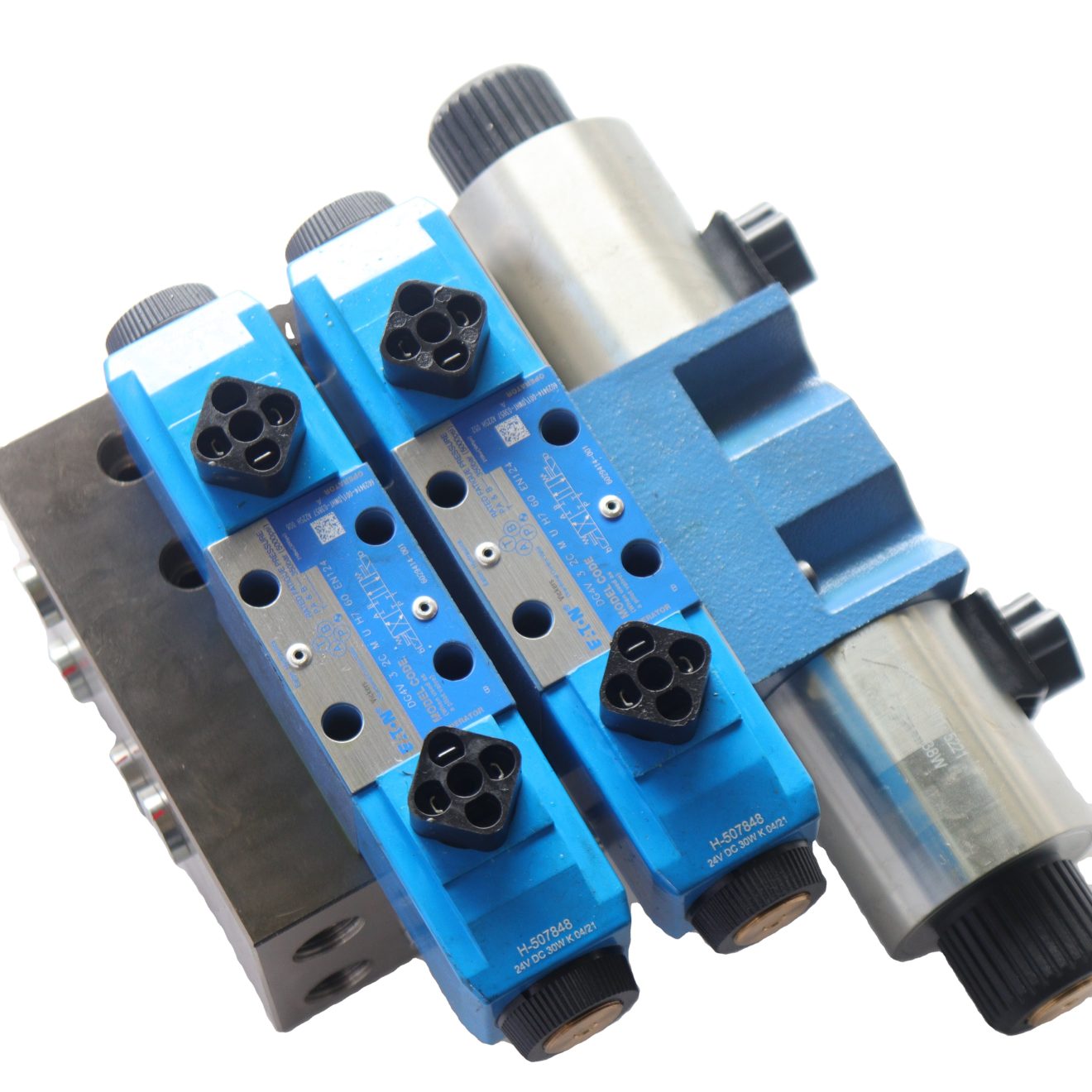
Processing and manufacturing of high pressure manifold blocks
Preprocessing
The material used for machining the blocks must have a dense internal organisation and must be free from defects such as intercalation, trachoma, etc. The blanks should be flaw-probed if necessary. Cast iron blocks and larger steel blocks should be aged and pre-treated before machining.
Machining
After milling and planing the valve block blanks, perform clamping and scribing. Leave a margin for final fine grinding. The surface roughness of the valve block must meet the design requirements. This is especially important for hydraulic valves, flanges, and pipe fittings on the mounting surface. These surfaces should not have scribing marks or other defects. Otherwise, these imperfections will cause leakage.
Deburr
Valve block machining is completed. You must chamfer and deburr the valve block. Remove all burrs from the runners, especially at the intersections of connected runners. The reliability of the entire hydraulic system closely depends on this and cannot be ignored.
Cleanse
Before assembling the valve block, clean it thoroughly. Set up special cleaning equipment if possible. Use rust-preventive cleaning fluid, or alternatively, paraffin or motor oil. Flush the valve block with a certain pressure to ensure that you thoroughly clean all flow paths, especially blind holes. Make sure to remove all iron filings, dirt, and debris. Assemble the cleaned valve block immediately. If immediate assembly is not possible, coat the valve block with anti-rust oil and cover the oil port to prevent rusting and re-contamination.
Fit together
Before assembling the valve block, proofread it again to check whether the aperture connectivity matches the original drawings. Verify all components and parts before installation to ensure that they meet qualification standards for assembled components, seals, and other parts. Seal the screw plug on the valve block with anaerobic adhesive. Before applying the adhesive, remove any grease from the combined surface. Tighten the plug with the adhesive and allow the oil to pass only after 24 hours.
Commissioning of high pressure manifold blocks
Debug the high-pressure manifold blocks by flushing the circuit for 10 to 20 minutes beforehand. During the flushing, continuously switch the valve block on the electromagnetic commutation network to ensure that the oil flow reaches all channels of the valve block. If the valve block has proportional valves and servo valves, first modify the flushing plate to prevent damaging the precision components. The commissioning of the valve block includes pressure resistance test and function test. The test can use the system itself oil source can also use a special test bench.
Pressure resistance test
Select the test pressure for high-pressure manifold blocks based on the system’s working pressure Ps, as shown in Figure 1. Perform the pressure resistance test by gradually increasing the pressure. Once you reach the test pressure, hold it for 5 to 10 minutes. Ensure that all connecting surfaces are leak-free. Cauchy typically uses conventional components for the test bench or hydraulic system. Therefore, the test pressure is generally not more than 31.5 MPa.
| Table 1 Comparison table for test pressure selection | |||
| work pressure Ps/MPa | ≤16 | >16~25 | >25~31.5 |
| test pressure Ps/MPa | 1.5Ps | 1.25Ps less than 24MPa according to 24MPa test | 1.15Ps less than 31.5MPa according to 31.5MPa test |
If you find leakage on the combined surface of the hydraulic valve and the valve block during the pressure resistance test, identify the cause of the leakage and address the problem appropriately. Avoid using sealant on the combined surface to plug the leakage. During the pressure resistance test, adjust the pressure regulating spring of the pressure valve in the valve block circuit to its loosest setting, and set the throttle valve to its maximum. After the pressure resistance test, adjust the relief valve and safety valve on the valve block to the system’s set pressure.

Functional tests
Each valve in each circuit on the valve block should be functionally tested against the hydraulic system schematic. First of all, the test circuit of the P, T, A, B, X, Y oil port connection, the rest of the circuit of the oil port temporarily blocked with a screw plug or valve cover flange. Generally, you can connect the relief valve for loading. If the circuit includes a proportional valve, speed control valve, or throttle valve, connect these components to the hydraulic cylinder or hydraulic motor for testing. After adjusting the pressure of the P port on the valve block to the working pressure, test the action function of the circuit, and require the accurate and reliable action of each component. Adjust the pressure valve and pressure relay on the valve block to the system’s set pressure and lock them in place.
For decompression methods, ensure that when the external load changes, the overshooting value complies with the standard. Valve block on the solenoid valve neutral function should be correct, sensitive commutation, action can be Jing, and to repeat the test many times (more than 5 times). Adjust the speed control valve, throttle valve, proportional valve, and servo valves on the valve block, and observe how the output flow changes with the input signal. When encountering faults during commissioning, do not rush to dismantle for inspection. First, analyze the principle and list the various factors causing the failure. Check each factor one by one, starting with the main issues. Additionally, use pressure measuring joints to detect the actual pressure at key points. After the function test, block the exposed oil port in time to prevent the intrusion of dirt.
Concluding remarks
High-pressure manifold blocks have made a qualitative leap in the integration of hydraulic systems. They simplify the installation of the system and increase the reliability of system operation. Domestic hydraulic manufacturers have designed and manufactured various hydraulic systems and high-pressure manifold blocks. They have gradually formed standardized products and stereotypes.
For more information on valve blocks and valve parts, please continue to follow us. If you need help or guidance in selecting the most suitable hydraulic valve for your project, please contact us at Nanjing Zhuoyi Control Technology Co.