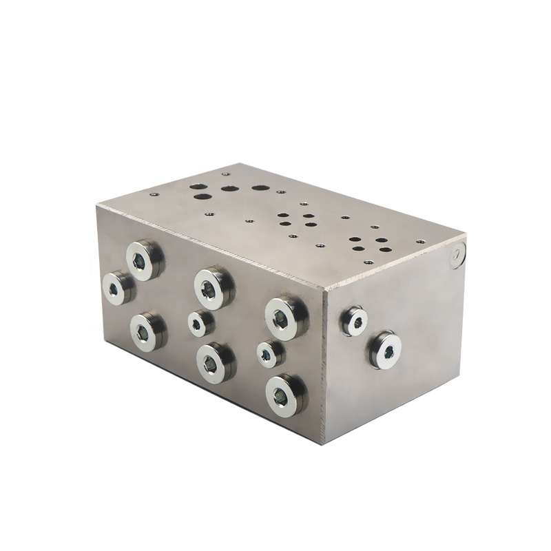
Introduction of hydraulic junction manifold
Principle of hydraulic junction manifold
The hydraulic junction manifold integrates selected hydraulic control valve parts. These are mounted on the same metal block body. They form an assembly with predetermined control functions. The valve block installs specific hydraulic control valves. It processes the internal oil circuit as per design requirements. The block forms a metal body with predetermined functions.These functions are inside the main and pilot orifices. The main level orifice controls fluid flow in the valve block. It connects to hydraulic power source, main return oil, and hydraulic actuators in the working chamber. Pilot orifice controls fluid flow in the valve block.It corresponds to oil inlet, return, drain, and pressure detection.
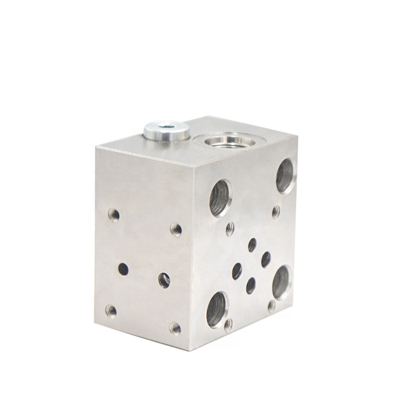
Classification of hydraulic junction manifold
(1) Hydraulic junction manifold can be divided into bar block, small plate block, cover plate, clamp plate according to the structure.
(2) According to the use of the valve, the hydraulic junction manifold divides into valve mounting plates, pump valve blocks, logic valve blocks, stacked valve blocks, special valve blocks, collector drains, connecting blocks, and other forms.
The actual hydraulic system of the hydraulic valve block by the valve block body and its installation of a variety of hydraulic valves, pipe fittings, accessories and other components.
Layout planning for hydraulic junction manifold
(1) The dimensions of the hydraulic components mounted on the hydraulic junction manifold shall not interfere with each other for easy maintenance;
(2) The geometric dimensions of the valve block mainly consider the external dimensions of the components mounted on the valve block, so that there is enough assembly space between the components;
(3) Consider whether the installation direction of the valve block is reasonable, and should make the valve spool in the horizontal direction to prevent the self-weight of the spool from affecting the sensitivity of the components;
(4) According to the system design requirements, determine the shape and position size of the common oil hole of the valve block. First, establish the installation parameters of the components on the valve block to avoid intersections with connecting orifices, and ideally, directly connect the orifices with the components.
(5) Orifices and mounting elements of the fixed screw holes, the minimum wall thickness between them for strength calibration;
The application of hydraulic junction manifold
The hydraulic junction manifold plays a very important role in the hydraulic system of the Centennial Palace ground cable car, mainly integrating the control valves that control the rail brakes and the related detection switches in the hydraulic valve block. Here we begin with the hydraulic aspects of the cable car compartment, showing the hydraulic diagram in Figure 1.
During normal operation of the Centennial Palace ground gondola, the hydraulic system of the carriage overcomes the pressure of the disc springs to keep the rail brakes open. In an emergency, the hydraulic system pressure relief, rail brake under the action of the disc spring clamped on the track to stop the cable car. The cable car hydraulic system is fed by both motorised gear pumps and hand pumps. Pressure switches control the start and stop operations. They ensure the rail brake is open. Limit switches adjust jaw size. This maintains braking distance within specification. To allow the motor to work without load, the control system energizes the solenoid valve. This opens fully, allowing hydraulic oil to flow directly back to the tank. After 3 seconds, the control system de-energizes and closes the solenoid valve, opening the inlet circuit to supply the system with oil, which opens the rail brake.
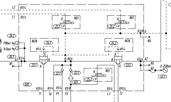
The valve block is a small hydraulic circuit that uses a variety of valves, collecting oil through the valve block’s oil holes. As shown in Figure 1, L1 and L2 are integrated valve blocks. For example, we are now using a balancing valve block. It includes balancing valves, pressure-reducing valves, safety valves, check valves, directional valves, and shuttle valves.
Integrated hydraulic valve block has functions on six surfaces. Physical and schematic diagrams (Figure 2, Figure 3) show each surface’s function.
(1) Top and bottom surfaces
The top surface and the ground surface stack together, and the surface features a common pressure oil port P, a common oil return port O, a leakage oil port L, and four bolt ports.
(2) The right side features frequently adjusted components:Pressure control valves include relief valves, pressure reducing valves, sequence valves. Flow control valves include throttle valves, speed control valves, etc.
(3) When installing directional valves on the front side, such as electromagnetic directional valves and check valves, position them for easy adjustment. If pressure and flow valves cannot be installed on the right side of the valve group, consider alternative placements.
(4) On the rear side, install directional valves and other components that do not require adjustment.
(5) The left side features an output oil port for connecting the actuator. External pressure points are included, along with auxiliary oil lines such as accumulator holes and oil holes for connecting the standby pressure relay.
(6) Outside pressure point and other auxiliary oil ports.
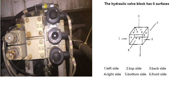
Combined with hydraulic diagrams and physical drawings. It is clear that the carriage hydraulic valve block concentrates a variety of hydraulic components. These include check valves, pipeline oil lines, cartridge valves, and more. The hydraulic valve block integrates them together, which plays a vital role in optimising the hydraulic oil circuit and facilitating installation and maintenance.
Common faults and design considerations of hydraulic junction manifold
Common failures of hydraulic junction manifold
(1) performance degradation: about 15% of the failure;
(2) performance degradation: approximately 70% of failures are primarily due to corrosion and mechanical wear. Mechanical wear further categorizes into abrasion, aging, and bonding damage.
(3) accidents: about 15% of the failure.
Considerations for Designing Hydraulic Junction Manifold
Hydraulic junction manifold design should prioritize simplicity in the oil circuit. Minimize deep, slant, and process holes effectively. To match the flow in the valve block aperture. Special attention should be paid to ensure that the hole has enough through-flow area. Consider the direction and location of the inlet and outlet, matching them with the overall layout of the system and pipeline connection form. Consider the installation and operation technology. Ensure components are installed vertically or horizontally as required. The installation must meet specifications.When adjusting components, prioritize designing for ease of operation and observation. For example, place relief valves in accessible positions. Position speed control valves similarly for easy operation.
Contact Zhuo Yi Control Technology for the latest production technology!