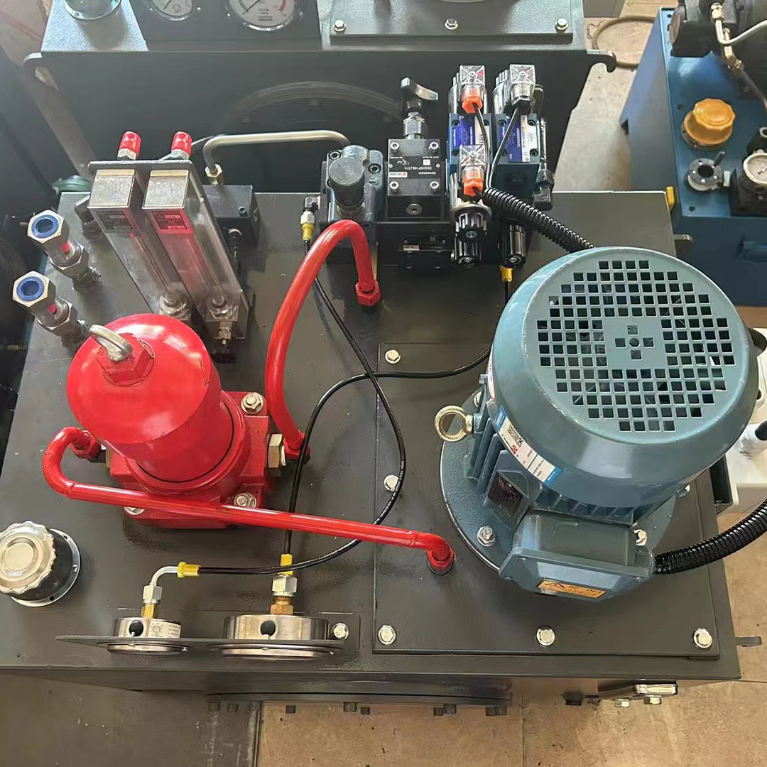
Figure 6-2 shows the hydraulic system installation process.

Figure 6-2 Hydraulic System Installation Process
According to the flow chart, figure 6-1 summarizes the precautions in the installation process. Various industries have implemented ISO 9000.Consequently, these industries have established technical specifications for installing hydraulic systems. They have also developed quality assurance systems to support these specifications. For instance, the metallurgical industry has formulated technical specifications for hydraulic system installation. The ground transportation industry has also developed its own specifications.
Similarly, the shipbuilding industry has established its guidelines. The chemical industry has set its own standards as well. The military industry and aerospace industry have also created technical specifications for hydraulic system installation. To ensure the successful execution of hydraulic system installation projects, professionals must adhere to the industry’s specifications. They must also follow the quality assurance systems established for these projects. But Figure 6-1 list of precautions is still the installation of the practice needs to pay attention to the content.
Figure 6-1 Hydraulic System Installation Considerations
| Serial number | Process stage | Caveat | Specific technical measures |
| 1 | piping | Easy installation and maintenance | Depends on proper design and pipework |
| Guaranteed leak-free | Welding process guarantee, joint form reasonable choice; new system does not allow the use of raw tape and anti-leakage glue | ||
| Piping meets requirements | The oil return pipe is placed below the liquid level to prevent air from being brought in; the oil pipe of the pump valve must return independently to prevent leakage.Suction pipe is not allowed to leak; relief valve oil return to avoid direct linkage pump, but should be returned to the tank: long pipeline needs bracket, to avoid pipeline resonance noise; the highest place should be equipped with an exhaust device: pipeline generally need to be installed for the second time, i.e., trial installation and formal installation | ||
| Flexible tube | Reasonable bending radius; avoid contact with other machinery and piping machinery | ||
| 2 | Pipe flushing | Tank cleaning | degreasing – rinsing with water – pickling -rinsing with water – neutralisation – passivation- rinsing and drying with water – secondary installation |
| Cycle washing | water test leakage – degreasing – water rinse – pickling – neutralisation – passivation – water rinse – drying – secondary installation;to avoid precision hydraulic parts flushing;the original pump is not for flushing pumps,you can use centrifugal pumps; flushing the system after the removal of the original cartridge | ||
| 3 | hydraulic station | Oil tank | Placement in a well-ventilated location to facilitate heat dissipation |
| Electric motor pump set | Ensure that the coaxiality (take 0.05), rotate freely; generally use flexible couplings to connect the ground foundation and skeleton rigidity is firm and reliable; pay attention to the required direction of rotation | ||
| Hydraulic Valves | Prior to the test pressure, action normal,easy to operate and observe; attention to proportional, servo valve anti-interference environment | ||
| Hydraulic accessories | Pay attention to the aging of rubber parts(e.g. accumulator bladders, etc.); use inflatable tools to inflate nitrogen on inflatable accumulators. | ||
| Seals | Ensure the installation surface is free of burrs, and chamfer or guide the grooves. Coat the seals with grease during installation; pay attention to the sealing ring retaining ring and its own sealing directionality; the installation of V or L-shaped ring compression force is appropriate; We should use a special tool to push the oil encapsulation into the seat hole to prevent it from skewing. | ||
| 4 | mounting element | All parts | We should clean the test element with paraffin during installation; tighten the fixing screws diagonally according to the required torque. |
| Hydraulic cylinder | Installation according to the requirements of the host For large diameter hydraulic cylinders with a stroke of 2 to 2.5 meters or more, the installation requires specific components. You must include a piston rod guide support ring. Additionally, you need to provide support in the middle of the cylinder itself.To prevent deflection of the piston rod and cylinder, ensure proper tightening of the gland screw. This adjustment helps maintain smooth movement of the piston throughout its entire range. It also prevents stagnation and uneven weight distribution. Screws too tight will increase resistance, accelerate wear; too loose will cause oil leakage | ||
| 5 | test pressure | Must be pressure tested | Test pressure can be the original pump, you can also use a special pump; test pressure according to design requirements |
| 6 | cleanliness | As per design and acceptance requirements |
Contact Zhuo Yi Control Technology for the latest production technology!