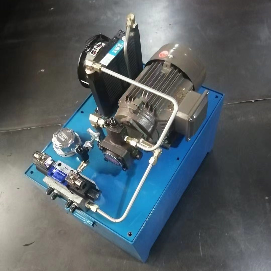
Structural characteristics of hydraulic valve manifold
According to the structure and use of the division, the hydraulic valve manifold has a bar block, small plate block, cover plate, plywood, valve mounting plate, pump valve block, logic valve block, stacked valve block, special valve block, collector drain and connecting block and so on a variety of forms. The actual hydraulic valve manifold system consists of a valve block body and various hydraulic valves, pipe fittings, accessories, and other components installed on it.
Valve body
Valve block body is the key component of the integrated hydraulic system, it is not only the other hydraulic components of the mounting carrier, but also their oil circuit connected to the channel body. We generally use a rectangular shape for the valve block body and select aluminum or malleable cast iron as the material. Distribute the hydraulic valve mounting holes, oil holes, connecting screw holes, and positioning pin holes on the valve block body.
Also, include public oil holes and connecting holes. Ensure that the holes connect correctly and do not interfere with the process of setting up holes. A relatively simple valve block body generally has at least 40 to 60 holes. A slightly more complex valve block can have hundreds of holes. These holes form a crisscrossing network of hole systems.The body of the valve block is designed with various types of holes.These include light holes, step holes, threaded holes, and other forms of straight holes.All these holes are easy to process.They can be processed with ordinary drilling machines.Additionally, they can also be processed with CNC machines.We occasionally set oblique holes for special connectivity requirements, but these are rarely used.
Hydraulic valve
Hydraulic valves are generally standard parts, including various types such as plate valves, cartridge valves, and stacked valves. We mount these valves on the valve block body using connecting screws to achieve the hydraulic circuit’s control function.
Pipe fitting
Use pipe fittings to connect external pipework to the valve block. You must connect the hydraulic circuit to external piping. This circuit is composed of various valves and valve block bodies. Connecting the circuit allows you to control hydraulic cylinders and other actuators. It also enables you to feed, return, and drain oil.
Other accessories
Includes accessories such as pipe connection flanges, process hole plugs, and oil line seals.
Layout principles for hydraulic valve manifold
The outer surface of the valve block body is the mounting surface of the valve element, and the inner surface is the space for the arrangement of the orifices. The six faces of the valve block form a collection of mounting surfaces. Normally, we do not use the bottom surface for mounting components; instead, we use it as a viewing surface for the tank or other valve blocks. In engineering practice, we usually use right angles for the installation angle of the hydraulic valve to facilitate installation and operation.
Functions of the six surfaces on the hydraulic valve manifold (for reference only):
(1) Top and bottom surfaces
The top and bottom surfaces of the hydraulic valve manifold are superimposed joint surfaces with a common pressure port P, a common return port 0, a leakage port L, and four bolt holes.
(2)Front, back and right sides
(a) the right side: the installation of frequently adjusted components, pressure control valves, such as relief valves, pressure reducing valves, sequence valves, etc.: flow control valves, such as throttle valves, speed control valves, etc..
(b) the front: When installing directional valves, such as electromagnetic directional valves and check valves, consider the following: If you cannot install the pressure and flow valves on the right side of the face, install them on the front. This arrangement will facilitate adjustment.
(c) Rear: Installation of non-adjustable elements such as directional valves.
(3) Left side face
Equip the left side with an output port for connecting the actuator. Include an external pressure measurement point. Add other auxiliary ports, such as an accumulator oil hole and an oil hole for connecting the backup pressure relay.
The planning of the spatial layout of the hydraulic valve manifold block is based on the design requirements of the hydraulic system schematic and layout drawings, etc. and the design experience of the designer. The general principles are as follows:
① The dimensions of the hydraulic components mounted on the hydraulic valve manifold shall not interfere with each other.
② Consider the geometry of the valve block primarily based on the external dimensions of the components to ensure there is enough assembly space between them. Ensure the distance between hydraulic components is greater than 5mm. Extend the solenoid on the directional valve, the pilot valve on the pressure valve, and the pressure gauge beyond the installation plane of the valve block to reduce the valve block’s volume. However, make sure that the outreach part does not touch other parts.
③ In the layout, you should consider whether the valve body’s installation direction is reasonable. Arrange the spool in the horizontal direction to prevent its self-weight from affecting the valve’s sensitivity. Especially, position the directional valve horizontally.
④ Determine the shape and positional dimensions of the common oil holes in the valve block based on the system’s design requirements. When determining the installation parameters for each component on the valve block, consider the best orthogonal hole connections. This will ensure direct connections and minimize unnecessary process holes.
⑤ Each element has more than two oil passage orifices. We need to connect these orifices to the orifices of other elements as well as to the common oil holes on the body of the valve block. As a result, we may find that a direct connection is not possible. In such cases, we must design the necessary process holes. Hydraulic valve manifold hole design involves several considerations. Determine the number of holes required and their types. Decide on the location, size, diameter, and depth of the holes on the valve block.
⑥ The minimum wall thickness between inaccessible orifices must be strength-checked.
⑦ Pay attention to the hydraulic components in the valve block. Ensure that the fixed screw holes do not touch the oil pipeline. The minimum wall thickness should also be checked for strength calibration and other factors.
Based on the above principles, the hydraulic valve manifold layout is optimised as follows:
(1) If the number of hydraulic elements on a face of the hydraulic valve manifold does not exceed 8, then we should arrange the hydraulic elements in the vicinity of each of the 4 corners. Additionally, we may arrange the other hydraulic elements in the vicinity of each of the 4 edges as appropriate.
(2) If the number of hydraulic elements on a face of the hydraulic valve manifold does not exceed 8, then we should arrange the hydraulic elements in the vicinity of each of the 4 corners. Additionally, we may arrange the other hydraulic elements in the vicinity of each of the 4 edges as appropriate. This ensures that we carry out the design of the process holes in the vicinity of one or two edges.
(3) If the number of hydraulic components on a face of a hydraulic valve manifold exceeds 8 or more, consider using intelligent methods for optimal design.
The hydraulic valve manifold normally contains no more than 10 hydraulic components. The number of hydraulic components assigned to each face does not exceed 10. Typically, it falls within the range of 3 to 5 components per face.
In general, hydraulic valve manifold design rarely involves arranging a large number of hydraulic components. Therefore, following the first two rules can meet the basic requirements of the system design.
Design Ideas for Hydraulic Valve Manifold
The hydraulic system principle forms the basis for designing the block-type integrated hydraulic control device and the integrated block unit circuit diagram. This principle essentially converts to an equivalent form in the design of the integrated block. Valve block drawings should include a corresponding schematic diagram. The schematic diagram should reflect the connectivity of the oil circuit. Additionally, it should mark the specifications of the components used, including the model, the name of the oil port, and the diameter of the aperture. This information is essential for designing the hydraulic valve manifold.
Before designing a valve block, first read through the schematic and then determine which part of the oil circuit you can integrate. The number of elements included on each block should be moderate. The size of the valve block body should be considered. Take into account the type and external dimensions of the components mounted on both sides. Additionally, ensure that you maintain the minimum permissible wall thickness between the holes in the oil path. This applies to the block body. You should strive for a compact structure, small size, and light weight while doing this.
Hydraulic valve manifold design principles
Hydraulic valve block design principle is the most important is the hydraulic valve block oil circuit in line with the hydraulic system schematic diagram.
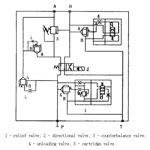
Before designing the valve block, determine which part of the oil circuit can be integrated. The number of components included in each block should be moderate. If the components are too many, the valve block will have a larger volume, and the design and processing will be more difficult. Conversely, if there are too few components, the integration will be of little significance, leading to a waste of materials. Take the JISCO first steel mill billet continuous casting machine shear hydraulic system as an example. The hydraulic system uses cartridge valves to control the flow. The action precision requirements are high, and the system’s reliability puts forward high requirements for operation.
Valve block design system valve block principle is shown below
Hydraulic valve manifold design considerations
Hydraulic valve manifold design, the oil circuit should be as simple as possible, to minimise deep holes, slant holes and process holes. Match the aperture of the valve block to the flow by ensuring that the through-holes provide sufficient flow area. Pay special attention to the direction and location of the inlet and outlet, and ensure they align with the overall system layout and pipeline connections. Consider the installation and operational requirements. Determine whether the components need vertical or horizontal installation. Ensure that the installation meets all requirements.
Design the system to ensure the convenience of operating and observing the components that need adjustment. Place relief valves, speed control valves, and other adjustable components in positions where the adjustment handles are easily accessible. This arrangement will facilitate convenient operation. Components and key components such as proportional valves and servo valves should be located above or outside the valve block.
Place the components and key components, such as proportional valves and servo valves, on the top or outside of the valve block. This arrangement will facilitate disassembly and assembly. In addition, the design of the valve block should set up a sufficient number of pressure measurement points for the debugging of the valve block. For valve blocks weighing more than 30kg, lifting screw holes should be provided. However, under the premise of meeting the requirements of use, the volume of the valve block should be as small as possible.
Relief valve: To protect the motor during startup or shutdown of the pump in the low-pressure zone, choose a solenoid relief valve. Additionally, to meet the high-pressure and high-flow work requirements, select relief valves with cartridges;
Reversing valve: Its role is to ensure that the hydraulic shear cylinder reverses smoothly and without impact. It also ensures that the system operates only when cutting is needed, thus avoiding malfunction.
Counterbalance valve: The role of this valve is to achieve translation control of the differential circuit. It is used for hydraulic shear to perform the cut-to-size operation when the cylinder is differential. During the billet shear process, the valve actuates to carry out the necessary actions.
Unloading valve: in order to ensure the rapid return of hydraulic shear, add a normally closed valve in the bypass, this valve only works when the hydraulic shear return;
Cartridge valve: cartridge valve is selected as a differential control.
Contact Zhuo Yi Control Technology for the latest production technology!