
Throughout the domestic and foreign solenoid valve hydraulic, so far, from the action can be divided into three categories: direct-acting, recoil, pilot operated, and from the valve structure and materials on the different principles of difference recoil can be divided into: diaphragm recoil solenoid valve, piston recoil solenoid valve; pilot operated can be divided into: pilot operated diaphragm solenoid valve, pilot operated piston solenoid valve; from the seat and the sealing material can be divided into: soft sealing solenoid valve, steel sealing solenoid valve, semi-steel sealing solenoid valve. Sealed solenoid valve, steel sealed solenoid valve, semi-steel sealed solenoid valve.
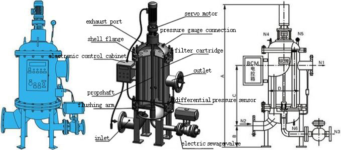
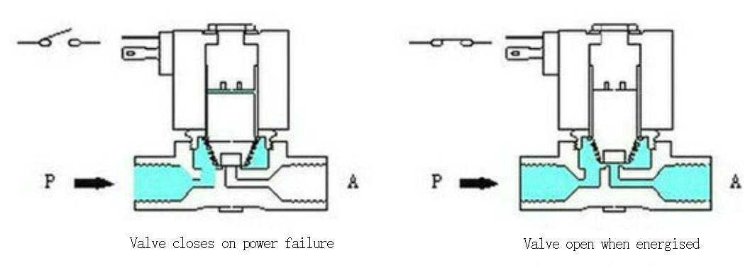
Directly operated solenoid valve hydraulic
Principle: In a normally closed direct-acting solenoid valve, when energized, the solenoid coil generates electromagnetic suction to lift the spool. This action moves the closure away from the valve seat, causing the valve to open. When power fails, the electromagnetic force disappears, and the spring force presses the closure back onto the valve seat, causing the valve to close. (Normally open type is opposite to this)
Characteristics: It can work normally in vacuum, negative pressure, and zero differential pressure. You can install it arbitrarily below DN50, but the solenoid head has a large volume.
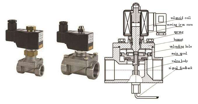
Backflush type solenoid valve hydraulic
Principle: Its principle combines direct-acting and pilot mechanisms. When you turn on the power, the solenoid valve first opens the auxiliary valve. The pressure in the main valve cavity becomes greater than the pressure in the upper cavity, using differential pressure and the solenoid valve to open the valve simultaneously. If power fails, the auxiliary valve uses spring force or medium pressure to close the parts, causing the valve to close as it moves downward.
Characteristics: It can work reliably at zero differential pressure or high pressure, but the power and volume are large, and it requires vertical installation.
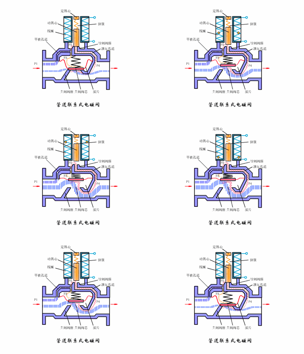
Pilot Operated Solenoid Valve Hydraulic
Principle: When the power is on, the electromagnetic force drives the pilot valve to open. This causes the pressure in the upper chamber of the main valve to drop rapidly. As a result, a pressure difference is created between the upper and lower chambers of the main valve. The medium pressure then pushes the main valve closure piece upward, causing the valve to open. When the power is off, the spring force closes the pilot valve. Consequently, the inlet medium pressure quickly enters the upper chamber of the main valve through the pilot holes. This forms a pressure difference that causes the main valve to close.
Characteristics: small size, low power, but the range of media differential pressure is limited, must meet the differential pressure conditions.
You usually use a two-position three-way solenoid valve in conjunction with single-acting pneumatic actuators. The two positions are controllable for on-off states, and the three-way configuration has three channels for ventilation. Generally, one channel connects to the air source, and the other two channels connect to the actuator’s inlet and exhaust ports. For the specific principle of operation, refer to the diagram of the single-acting pneumatic actuator’s operation.
You usually use a two-position five-way solenoid valve in conjunction with double-acting pneumatic actuators. The two positions are controllable for on-off states, and the five-way configuration has five channels for ventilation. One channel connects to the air source. Two channels connect to the inlet and outlet of the double-acting cylinder’s external chamber. The remaining two channels connect to the inlet and outlet of the internal chamber. You can refer to the principle of double-acting pneumatic actuators for the specific working principle.
In the gas circuit (or liquid circuit), two three-way solenoid valve hydraulic has 1 inlet hole (connected to the inlet air source), 1 outlet hole (provided to the target device air source), 1 exhaust hole (generally installed a muffler, if you are not afraid of the noise can not be installed @_@). The two-position five-way solenoid valve features one inlet hole, which is connected to the inlet air source. It includes one positive-action outlet hole and one negative-action outlet hole, which supply air to the positive and negative actions of the target equipment. Additionally, the valve has one positive-action exhaust hole and one negative-action exhaust hole, each equipped with a muffler.
For small automatic control equipment, you generally use 8~12mm industrial rubber gas pipes. Electrically, two three-way solenoid valve hydraulic is generally single electric control (i.e., single coil), two five-way solenoid valve is generally double electric control (i.e., double coil). You generally use DC24V or AC220V for the coil voltage level. Two three-way solenoid valve hydraulics divide into normally closed and normally open types. In the normally closed type, you close the gas path when you do not energize the coil. In the normally open type, the gas path remains open when you do not energize the coil.
The hydraulic action principle of a normally closed two three-way solenoid valve is as follows: When the coil is energized, the gas path is connected. Once the coil is de-energized, the gas path will be disconnected. This operation is equivalent to the ‘point of action’. In a normally open type two three-way single electronically controlled solenoid valve, the action principle is as follows: When you energize the coil, the air circuit disconnects. Once you de-energize the coil, the air circuit reconnects. We also call this “point action.” In a two-position five-way double electronically controlled solenoid valve, energizing the positive action coil connects the positive action airway. This connection supplies air to the positive action air outlet hole. Even if you de-energize the positive action coil, the positive action airway remains connected. You will maintain this state until you energize the reverse action coil.
If you energize the reverse action coil, it turns on the reverse action air circuit (supplying air to the reverse action air outlet). Even if you de-energize the reverse action coil, the reverse action air circuit remains on until you energize the positive action coil. This is equivalent to ‘self-locking’. Based on the characteristics of the two-position, five-way double electric control solenoid valve, you can design the electromechanical control circuit accordingly. Additionally, you can prepare the PLC program to match these characteristics. For protection of the solenoid valve coil, ensure that the solenoid valve coil is actuated for only 1 to 2 seconds. This helps prevent damage to the solenoid valve coil.
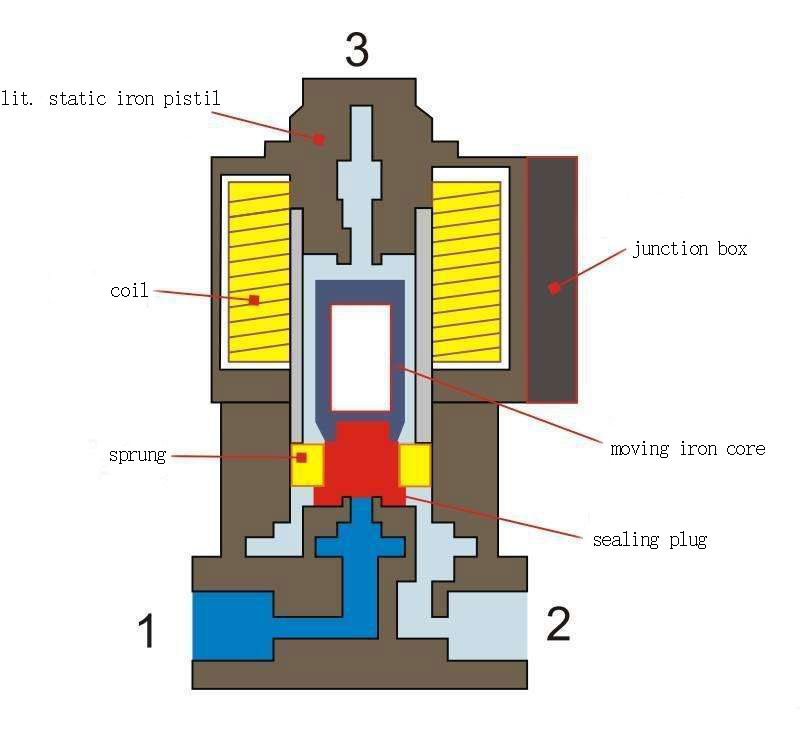
In a hydraulic liquid system, you use a solenoid valve to turn the liquid on or off or to change the direction of the liquid flow. It generally has a coil that drives a sliding spool with electromagnetic force. In different positions of the spool, the hydraulic paths of the solenoid valve change. The number of working positions of the spool determines the type of solenoid valve. If a solenoid valve has a certain number of working positions, it is referred to as a corresponding type of solenoid valve. Specifically, the valve body interface indicates the number of access points for the solenoid valve. Therefore, the number of through interfaces in the valve body defines the type of solenoid valve.
When you install a solenoid valve, you should connect all interfaces. The so-called working position refers to the position of the spool. When you do not energize the coil, the spool stays in the A position. When you energize the coil, the spool moves to the B position. In these different positions, the spool either connects or closes the interfaces.
Solenoid valve hydraulic two-position refers to the solenoid valve spool has two different working position (on, off). A solenoid valve can be classified as hydraulic two-way or three-way, depending on the number of channels in the valve body. For example, a two-way solenoid valve has one inlet and one outlet, which are the most common configuration. A three-way solenoid valve controls the flow of liquid with one inlet and two outlets, where one outlet is normally open and the other is normally closed. In a pneumatic directional solenoid valve, there is one inlet, one outlet, and one exhaust. For hydraulic applications, the valve typically has one inlet, one outlet, and one return oil port.
Domestic and foreign solenoid valve hydraulics divide into three major categories based on principle: direct-acting, step-by-step direct-acting, and pilot-operated. Additionally, you can classify them into six subclasses based on valve structure, materials, and principle differences: direct-acting diaphragm structure, step-by-step heavy piece structure, pilot diaphragm structure, direct-acting piston structure, step-by-step direct-acting piston structure, and pilot-operated piston structure.
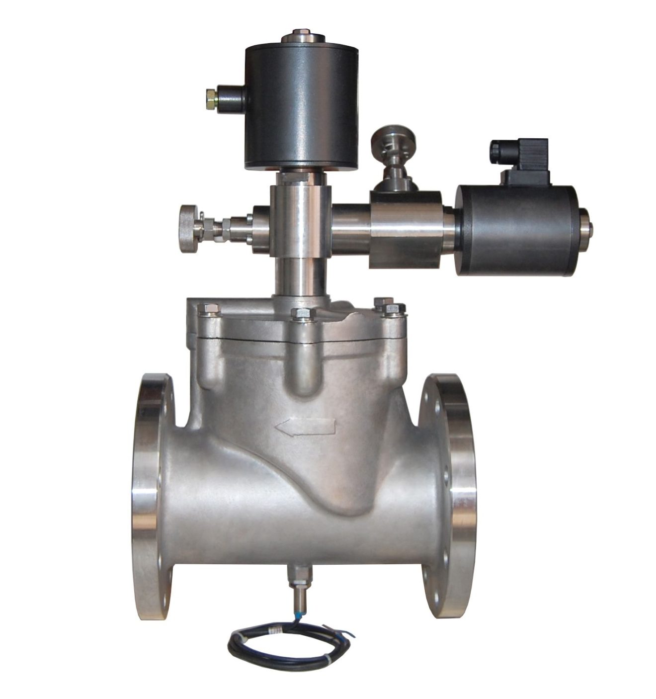
Direct-acting solenoid valve hydraulic:
Principle: When energized, the solenoid coil generates an electromagnetic force that lifts the closing piece off the valve seat. This action causes the valve to open. When de-energized, the electromagnetic force disappears, and the spring presses the closing piece back onto the valve seat. As a result, the valve closes.
Characteristics: It can work normally in vacuum, negative pressure and zero pressure, but the through diameter is generally not more than 25mm.
Distribution of direct-acting solenoid valve hydraulic:
Principle:It is a combination of direct-acting and pilot-operated principles. When there is no pressure difference between the inlet and the outlet, the electromagnetic force directly lifts the pilot valve after energization. This, in turn, causes the main valve closure piece to move upwards. As a result, the valve opens.
When you start the system, a pressure difference develops between the inlet and outlet. The power and electromagnetic force act on the pilot valve, causing the pressure in the lower chamber of the main valve to rise. At the same time, the pressure in the upper chamber of the main valve drops. This pressure difference pushes the main valve upwards. If power fails, the pilot valve uses spring force or medium pressure to push the closing member downward, which closes the valve.
Characteristics: In zero differential pressure or vacuum, you can also achieve high pressure, but you need more power, and you must install it horizontally.
Pilot operated solenoid valve hydraulic:
Principle: When energized, the electromagnetic force opens the pilot hole, causing the pressure in the upper chamber to drop rapidly. This creates a low pressure difference around the closing member. The fluid pressure then pushes the closing member upwards, causing the valve to open. When de-energized, the spring force closes the pilot hole. The inlet pressure then passes through the bypass hole rapidly, forming a lower-low upper-pressure difference around the shut-off member. This causes the fluid pressure to push the closing member downwards, closing the valve.
Characteristics: You can freely install (customize) for a high upper fluid pressure range, but you must meet the differential fluid pressure conditions.
Contact Zhuo Yi Control Technology for the latest production technology!


