Everyone is familiar with the injection moulding machine; it processes many plastic products we use in our daily lives.
The working principle involves heating and melting granular plastic to a flow state. We then inject it into the mould cavity quickly with high pressure and hold the pressure for a certain period. After cooling and solidification, the processing is complete.
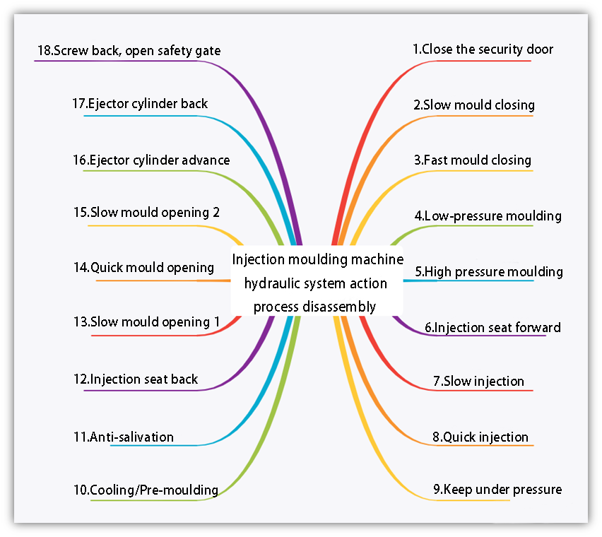
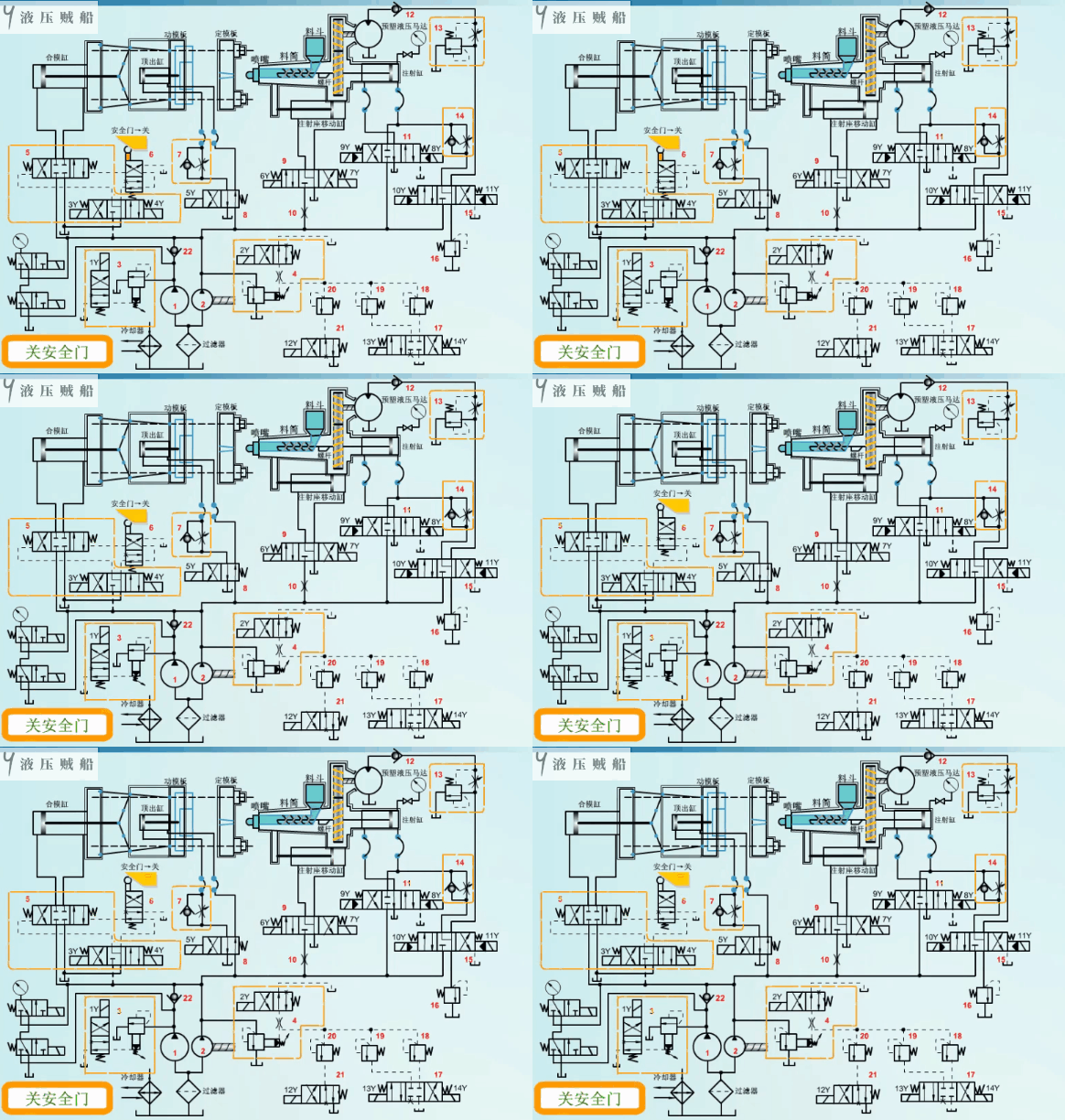
The injection moulding machine can achieve the above functions without the help of the hydraulic system. Today, we will disassemble the hydraulic schematic diagram of an ordinary injection moulding machine in detail to see the action process of each hydraulic component. Mainly divided into 18 steps, the following we analyse one by one.
Close the security door
In order to ensure the safety of operation, the injection moulding machine will be equipped with a safety gate, only when the safety gate is closed, other actions can be carried out normally, the key element is the travel valve 6 in the figure.
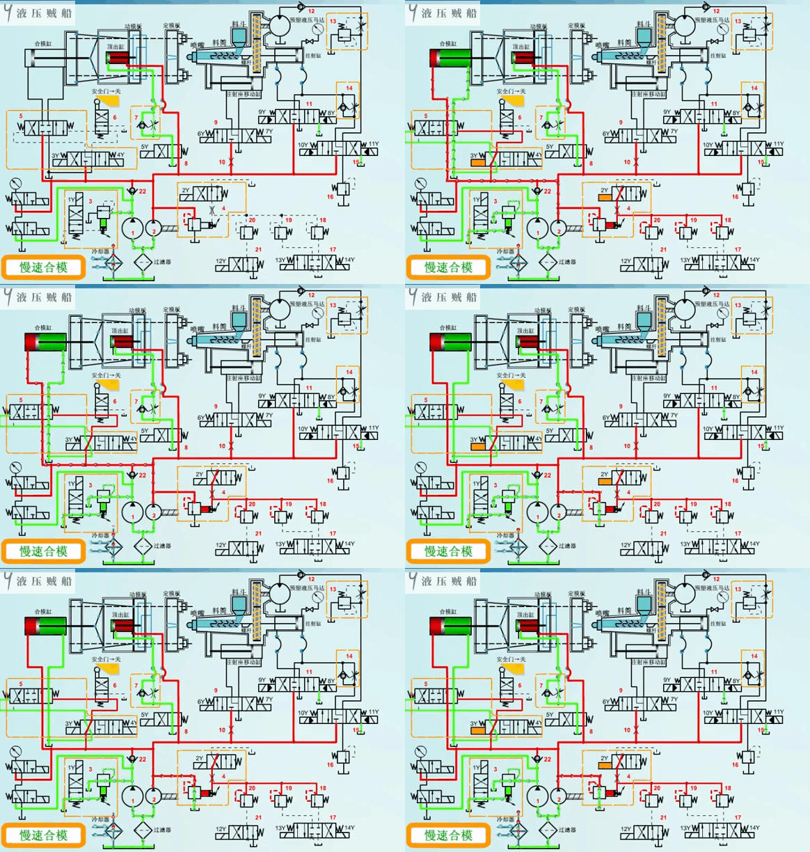
Slow mould closing
The clamping process can be divided into four stages: slow clamping, fast clamping, low pressure clamping and high pressure clamping. The advantage of this is that it shortens the empty stroke time and improves productivity, while avoiding possible shocks at the start and end positions.
During slow mould closing, only the rodless cavity of the clamping cylinder is supplied with oil by the small-flow pump 2, with the pressure regulated by valve 4, while the large-flow pump 1 is completely unloaded by valve 3. As the oil supply flow to the rodless cavity of the clamping cylinder is small, the operation speed is slow.
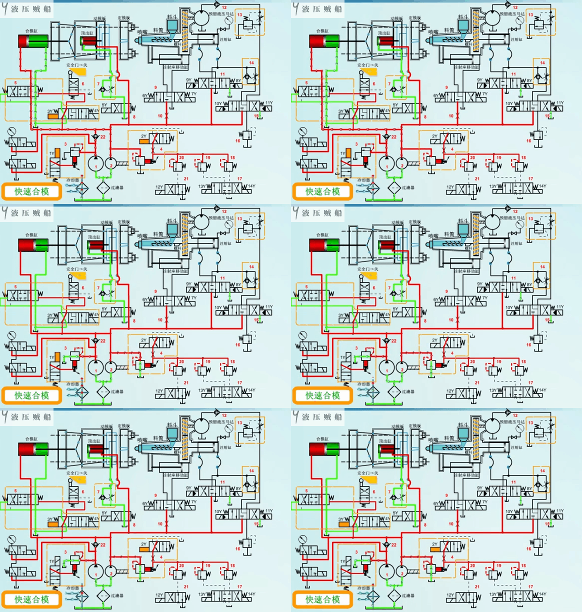
Fast mould closing
During fast mould closing, the clamping cylinder runs quickly to the right. We need to supply the rodless cavity of the clamping cylinder with a large flow rate during this process. For this reason, we supply the rodless cavity of the clamping cylinder with the flow from both the high-flow pump 1 and the low-flow pump 2, which naturally runs faster.
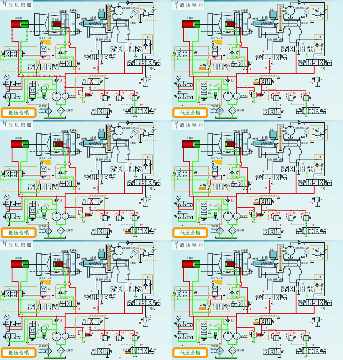
Low Pressure Moulding
When the clamping cylinder is about to run to the end of the stroke, in order to prevent the moving template and the fixed template due to the impact of the surface damage, and need to switch to a slow, low-pressure operating conditions. During this time, small flow pump 2 supplies the oil, with the pressure controlled by remote regulator 18. Meanwhile, we completely unload large flow pump 1 through valve 3.
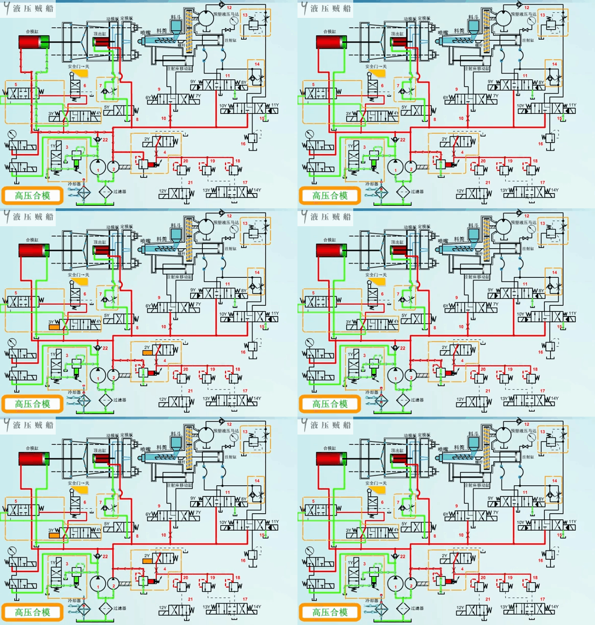
High Pressure Moulding
In order to prevent the overflow of the injection moulded part due to the gap between the moving plate and the fixed plate, we need to further use the clamping cylinder to push the connecting rod spreading mechanism to achieve the clamping and locking action. This process requires high pressure and low flow rate, so we continue to supply the oil with pump 2. We control the pressure using high pressure relief valve 4.
Injection seat forward
To ensure sufficient thrust during injection, we use a hydraulic cylinder to drive the injection seat. This setup ensures that the nozzle and the gate of the mould are in close contact with each other. This helps prevent the nozzle from experiencing the ‘drooling’ phenomenon.
In the process of moving the injection seat to the left, small flow pump 2 supplies oil to the rodless cavity of the injection seat moving cylinder. This causes the cylinder to move slowly. When the cylinder reaches the desired position, it is preferable to have a check valve. The check valve helps hold pressure and prevents the contact parts of the nozzle and the gate from loosening. However, the figure is not indicated, you need to pay attention to the design.
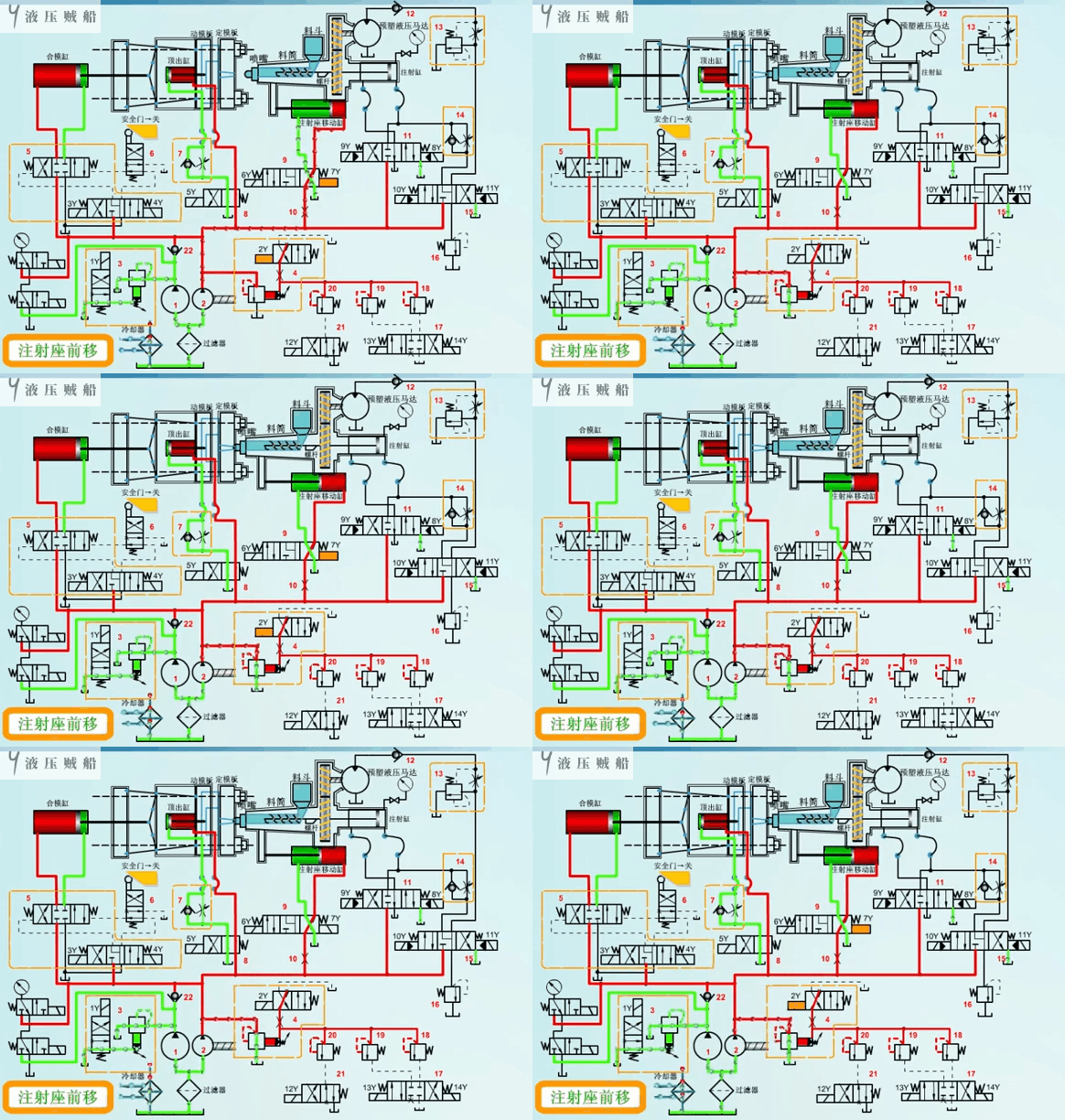
Slow Injection
We subdivide the injection process into two phases: slow and fast. During the slow injection phase, small flow rate pump 2 supplies oil to the rodless cavity of the injection cylinder. Of course, due to the different types of raw materials, the pressure and speed required for injection will also be different. We can control the pressure using remote regulator 20, while we adjust the speed with one-way throttle valve 14.
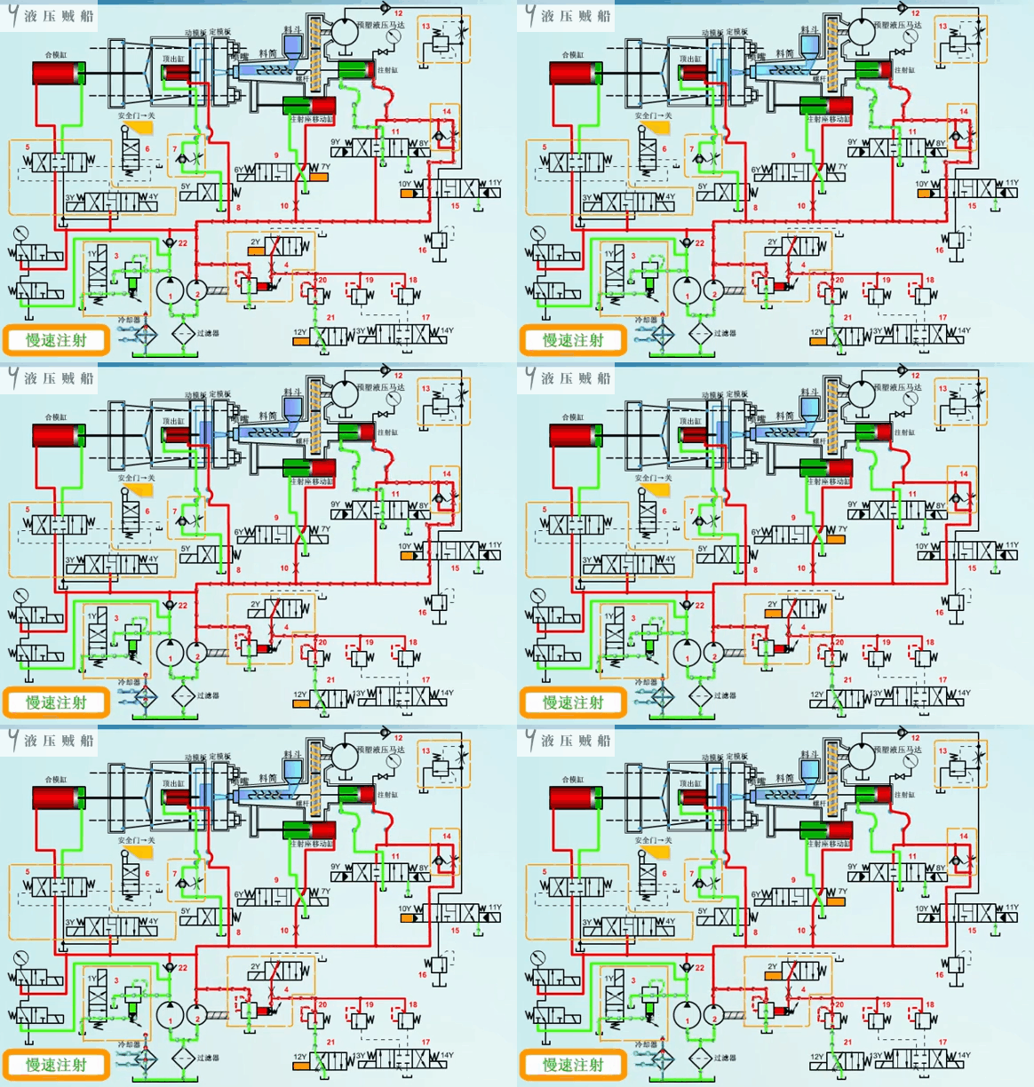
Quick Injection
For the rapid injection process, both large flow pump 1 and small flow pump 2 supply oil to the rodless cavity of the injection cylinder simultaneously. At this time, we need to pay special attention to ensure that reversing valve 11 operates in the correct position. This setup ensures that the oil from both pumps does not pass through the unidirectional throttle valve 14 but goes directly into the rodless cavity of the injection cylinder. The speed of the injection process becomes more apparent.
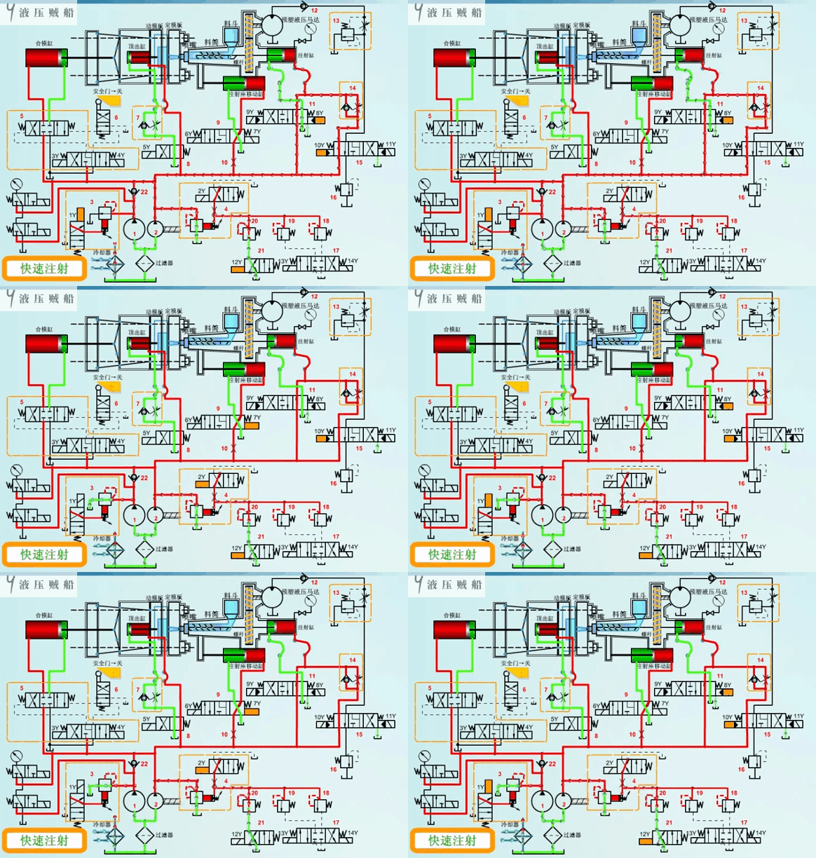
Keep under pressure
In order for the molten plastic to fill the cavity to obtain a precise shape, we therefore need to hold it under pressure.
During the holding pressure process, we use the pump’s output flow rate only to compensate for leakage. The flow rate does not need to be very large, so small flow rate pump 2 is sufficient. We set its holding pressure with the remote regulator 19.
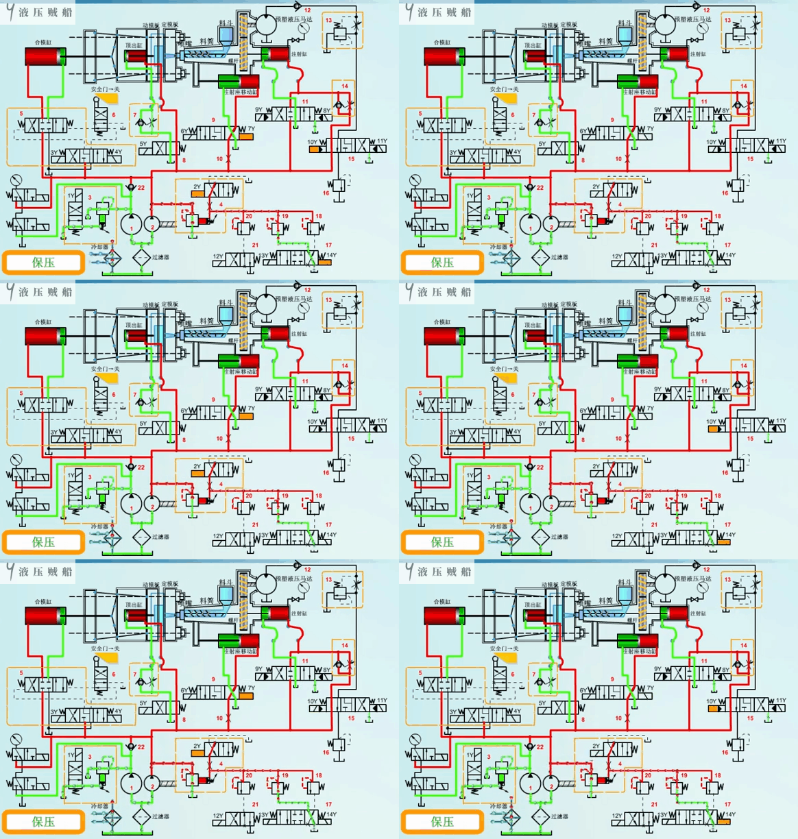
Pre-moulding
Pre-moulding involves using the time when the products in the mould cavity are cooling and holding pressure effectively. During this period, we can send the plastic granules from the hopper to the barrel in advance and heat them up for melting. This process is what we call pre-moulding.
During pre-moulding, we supply oil simultaneously with pump 1 and pump 2. These pumps drive the pre-moulding hydraulic motor, which then drives the screw, rolling the plastic granules from the hopper into the barrel. The speed of the motor can be adjusted by a throttle valve 13.
In addition, after we heat the plastic granules in the barrel, they generate a reverse force on the screw. This force causes the screw to move to the right, which in turn forces the injection cylinder to move to the right. At this time, the injection cylinder rod chamber will form a partial vacuum, which in turn draws part of the oil from the tank.
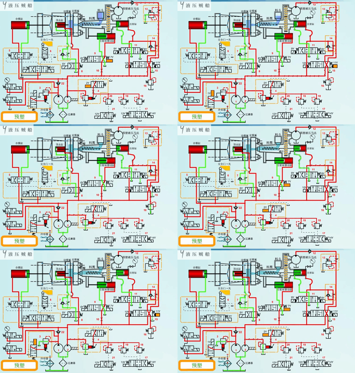
Anti-salivation
Salivation, similar to the drooling of children, involves supplying oil to the rod chamber of the injection cylinder with small pump 1. This action moves the screw slightly to the right, which in turn moves the melt a little to the right. At the same time, the injection seat moving cylinder should be in a pressure holding state to prevent dripping at the nozzle.
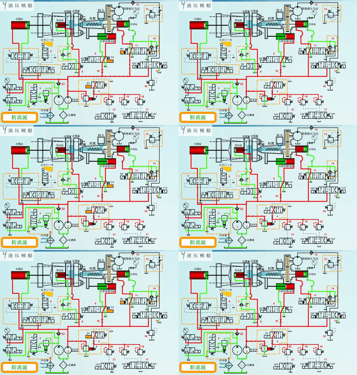
Injection Seat Back
When we finish the pressure holding, cooling, and pre-moulding processes, small pump 2 continues to feed the rod chamber of the injection seat moving cylinder. This action pushes the injection seat moving cylinder back to the rightmost end.
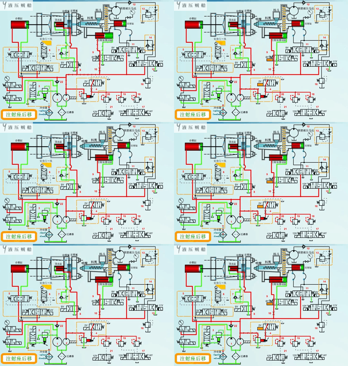
Slow mould opening 1
The mould opening process is also divided into three processes: slow mould opening 1, fast mould opening and slow mould opening 2.
During slow mould opening 1, only small flow pump 2 supplies oil to the rod cavity of the clamping cylinder, while we completely unload large flow pump 1.
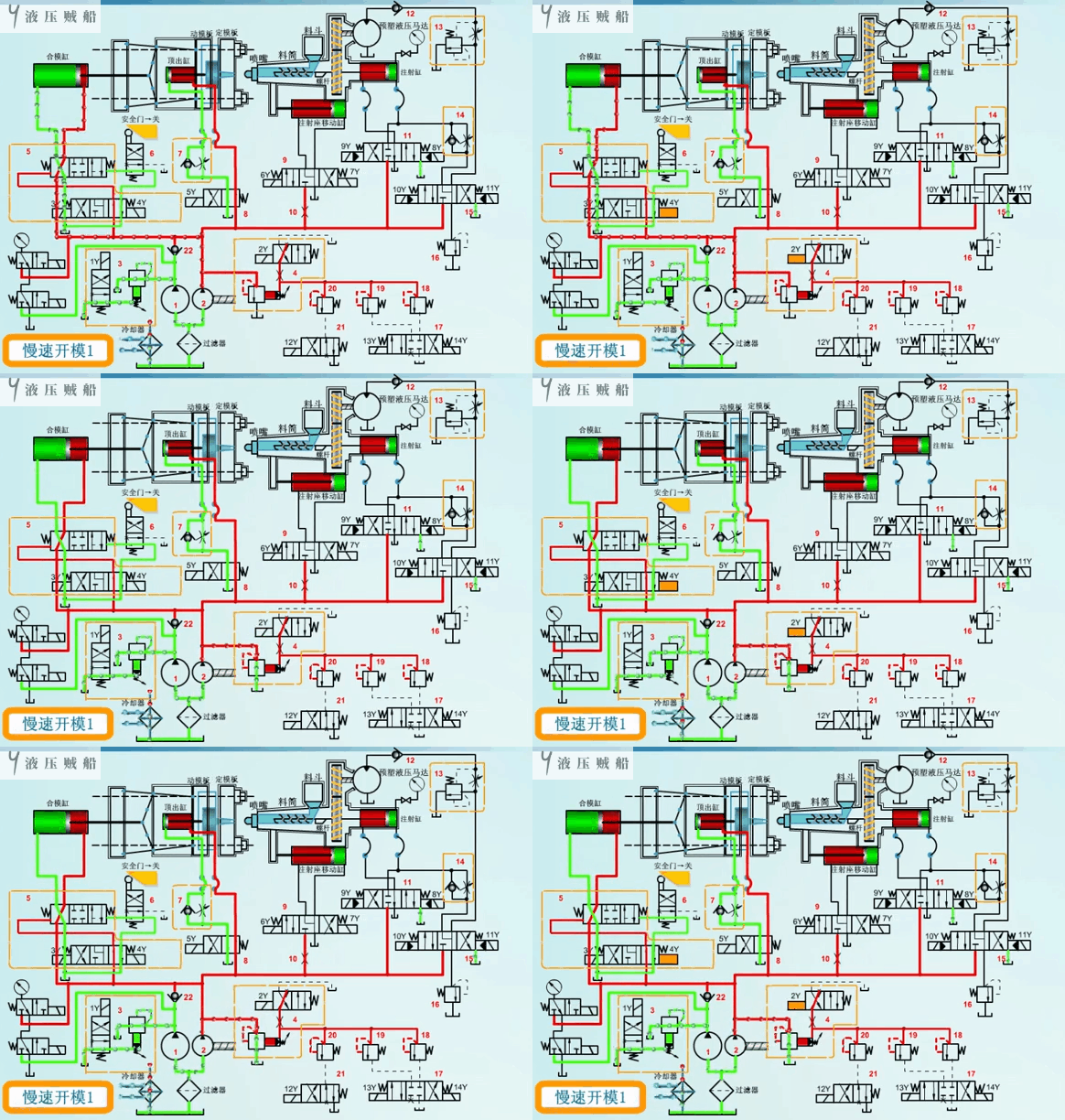
Quick mould opening
During rapid mould opening, large flow pump 1 and small flow pump 2 supply oil simultaneously to the rod cavity of the clamping cylinder. This causes the clamping cylinder to rapidly retreat to the left.
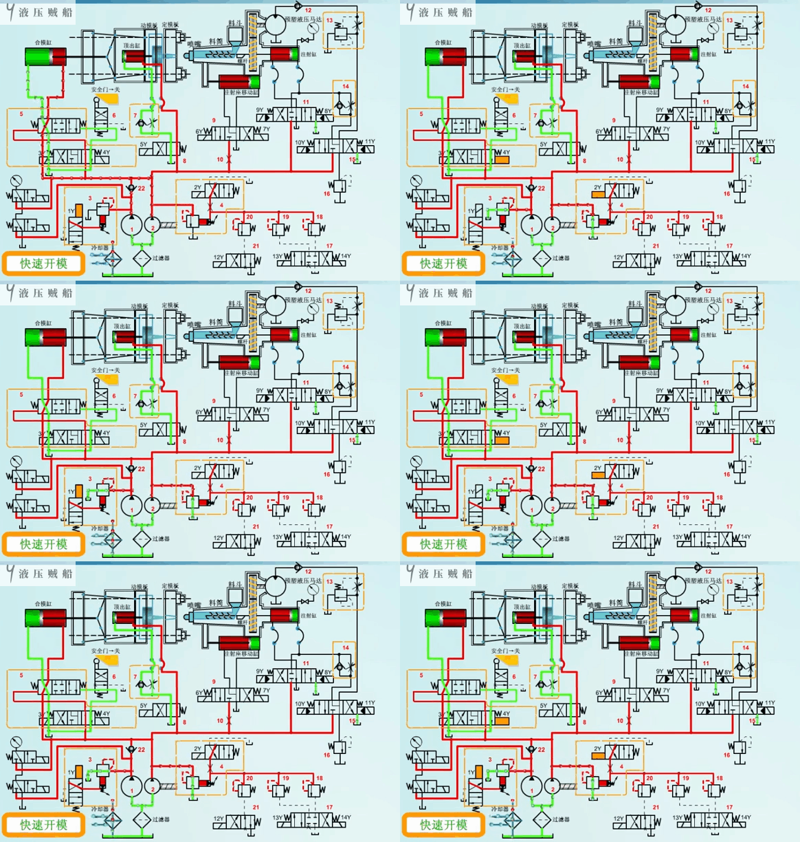
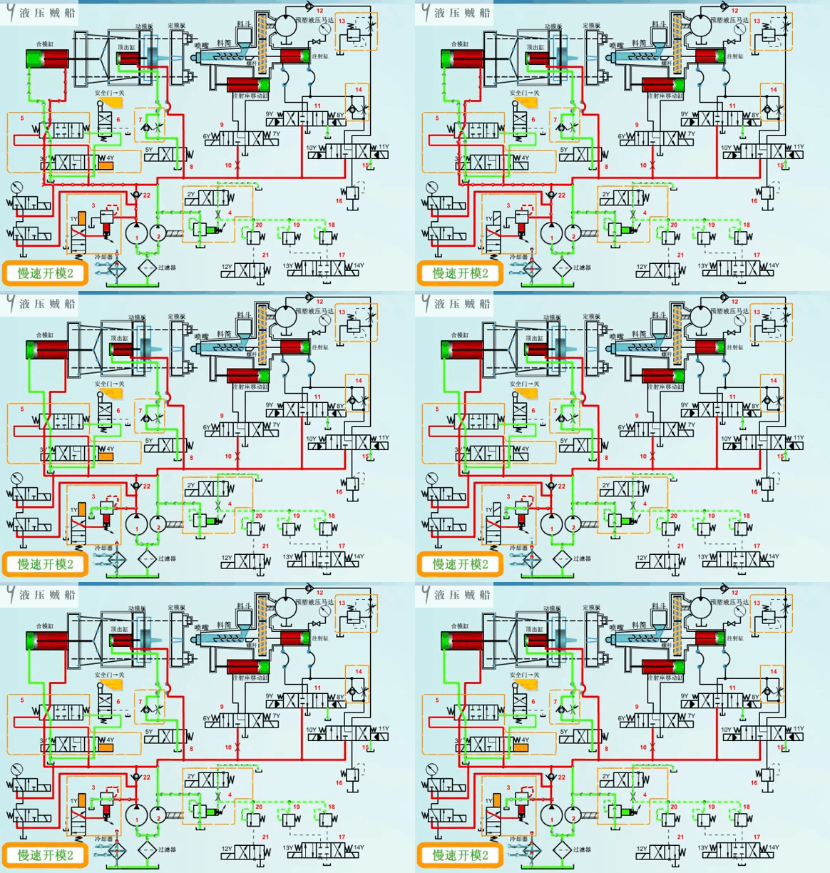
Slow mould opening 2
During the slow opening of the mould 2, small flow pump 2 still supplies oil to the rod chamber of the clamping cylinder. This action moves the clamping cylinder slowly to its initial position at the left end.
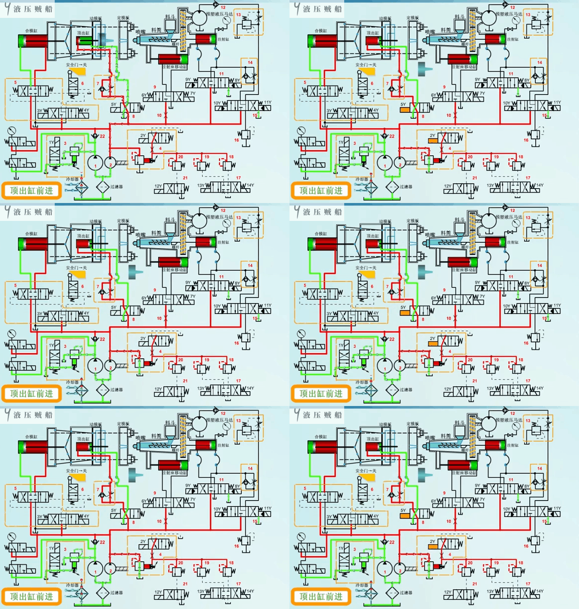
Ejector cylinder advance
Ejection involves removing a plastic product from the mould cavity after we have cooled and moulded it. We should note that, during ejection, we need to maintain a smooth speed to avoid damaging the product.
During the extension of the ejector cylinder, we supply oil to the rodless chamber of the ejector cylinder only with low-flow pump 2. We can adjust the extension speed using one-way throttle valve 7.
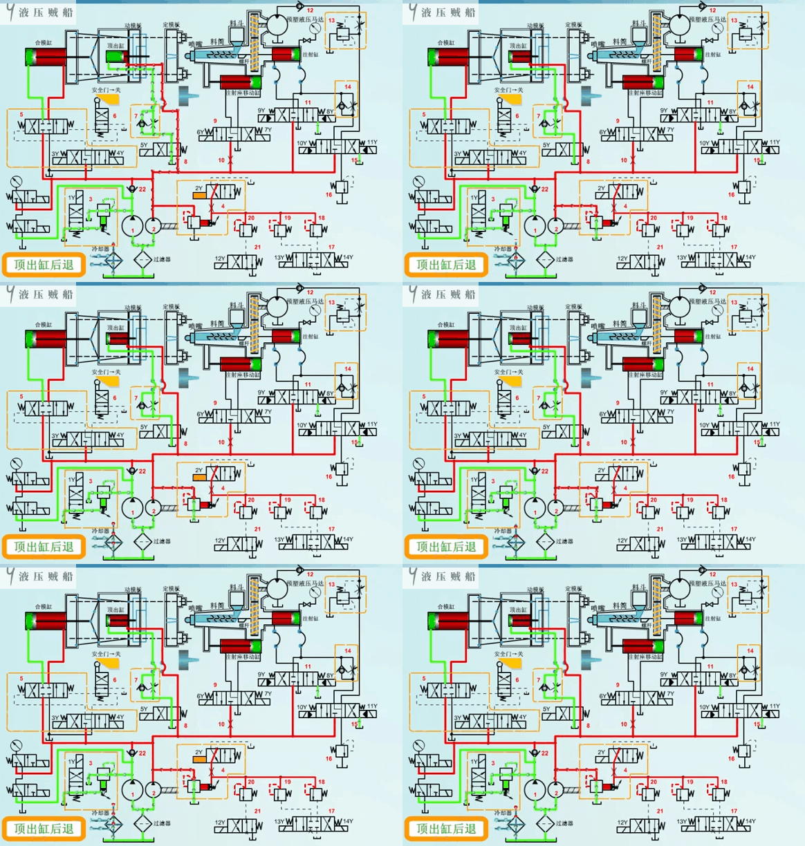
Ejector cylinder back
When we eject the plastic product, low flow pump 2 turns on. It supplies oil to the rod chamber of the ejector cylinder. This action returns the ejector cylinder to its initial position at the left end.
Screw backs off, safety door opens
Sometimes it is necessary to back off the screw in order to remove and clean it. We supply oil to the rod chamber of the injection cylinder. This process is nothing special and will not be repeated.
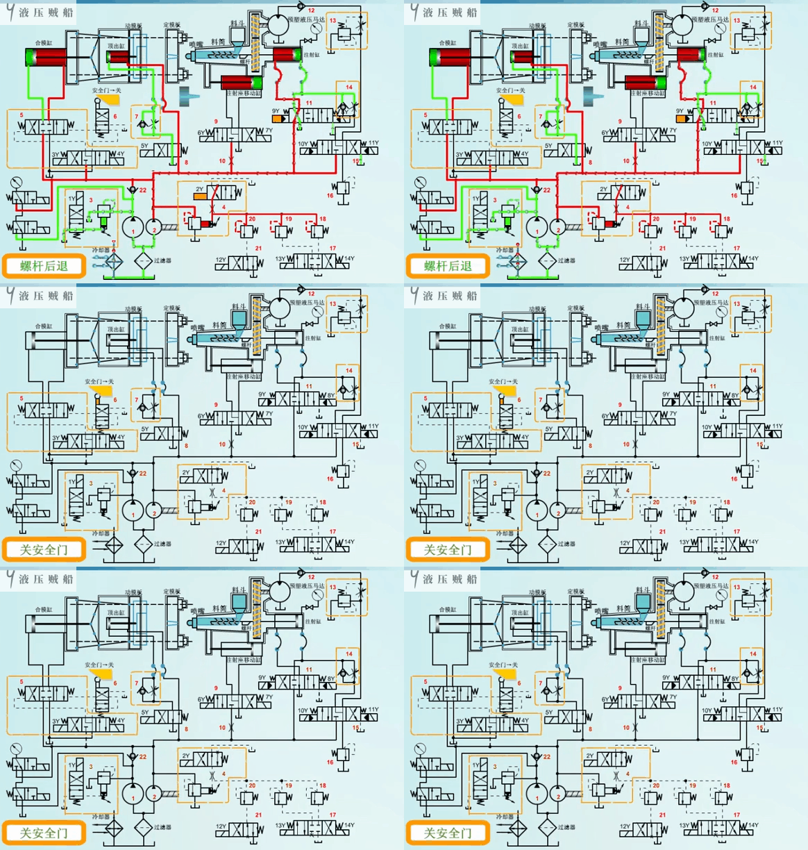
So far, we have run through the course of action of the hydraulic system of the injection moulding machine from beginning to end.
Contact Zhuo Yi Control Technology for the latest production technology!