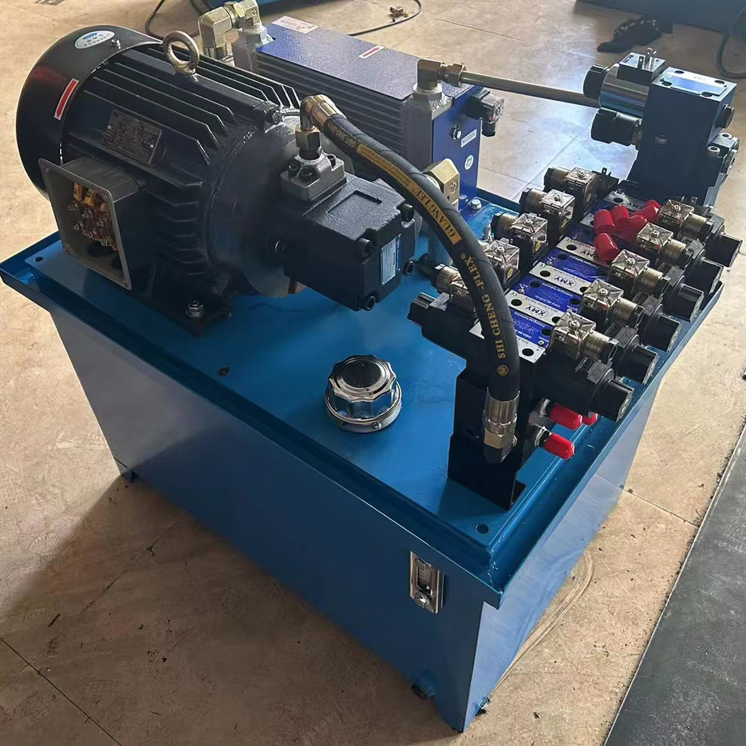
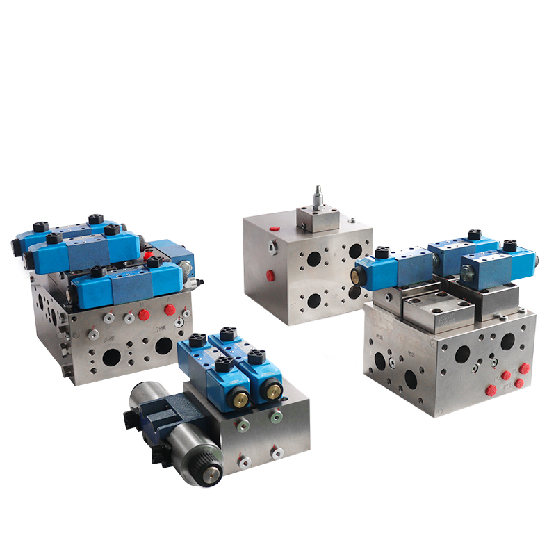
Today we are going to explain solenoid hydraulic control valves. Friends engaged in the electrical automation industry, not only to understand the control of electricity, but also need to learn the control of gas. Because electric motors can drive the control of equipment actions, you can also use compressed gas to control cylinder actions. The ‘solenoid hydraulic control valve’ is to control the cylinder switch.
Introduction of solenoid hydraulic control valve
We can literally understand the solenoid hydraulic control valve as follows. Valve: It is the switch. It can be opened or closed. Solenoid: It means that the switch is controlled by the suction of electromagnet. So the solenoid hydraulic control valve uses a solenoid to control the valve switch, and it controls fluid automation infrastructure equipment as part of the actuator. Used in industrial control systems to be able to adjust the direction of the fluid, flow, speed and other functions. Solenoid hydraulic control valve has many types, different solenoid valves in different positions in the control system play a role is also different. We mainly explain today is to adjust the direction of the fluid solenoid hydraulic control valve. Fluid contains gas and liquid.
The appearance of the solenoid valve and the meaning of the graphic symbols
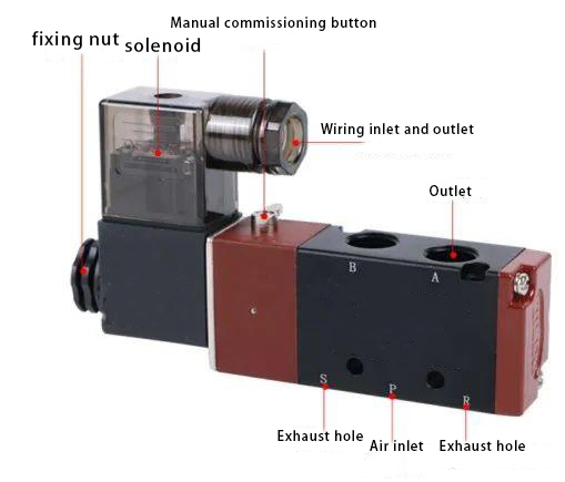
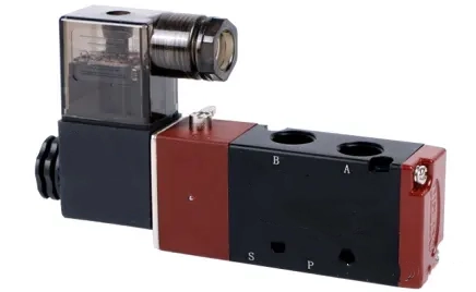
Take the two-position five-way solenoid valve as an example. We use (P) as the air inlet hole to connect the air pump or air source. We place two exhaust holes, R and S, on both sides of the P hole. To reduce the noise, you can connect a muffler. Above two holes outlet A, B. Received cylinder, R is the exhaust hole of A, S is the exhaust hole of B.
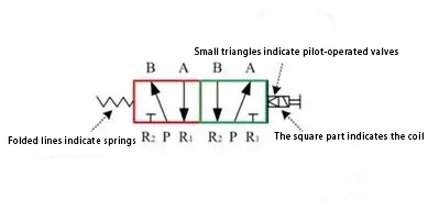
- A broken line indicates a spring, a square indicates a coil, and a small triangle next to it indicates a pilot operated solenoid valve.
- A box indicates the working position of the valve, and the number of boxes shows the number of ‘positions’. You can observe the number of squares on a solenoid valve to determine the working position of the spool. There are a few boxes is a few bits. For example, the following two boxes, shown in red and green, represent a two-position valve.
- a box inside the upper and lower connected to the number of intersections, that a few ‘through’. Likewise, the following figure for example, the red box and the upper and lower boxes connected to the intersection of the line has 5 that the electromagnetic 5 pass.
- The arrow in the box shows the current position of the gas circuit and the connected state. However, the arrow’s direction does not necessarily indicate the actual direction of the fluid.
- The symbol ‘T’ or ‘⊥’ in the box indicates that the gas line is not connected.
The working principle of the solenoid valve
The passage above introduces the working principle of the solenoid valve. To understand how the solenoid valve adjusts the direction of the fluid, you need to master its working principle. The solenoid valve requires control using cylinders or oil cylinders. Although the media—oil and gas—used for control are different, the principle remains the same.
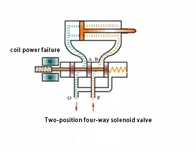
We control the cylinder of the direct-acting two-position four-way single-control solenoid valve as an example of introduction. Solenoid valve has a closed cavity, in different locations open holes, each hole connected to a different gas pipe, cavity in the middle of the spool is similar to the piston, (single-controlled valve is only one side of the solenoid, the other side is the spring).
When we energize the coil, it attracts the iron core and moves the valve core. By moving the valve core, the system opens or closes different exhaust holes. The inlet hole remains always open, allowing gas to enter different exhaust pipes. The gas pressure then pushes the cylinder’s piston. The piston drives the piston rod, and the piston rod, in turn, drives the mechanical device. In this way, by controlling the electromagnet current breaks control the mechanical movement.
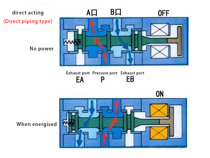
The solenoid valve’s operation relies on two principles: the direct-acting solenoid valve, which inventors introduced earlier, and the pilot-operated solenoid valve, which engineers gradually developed.
Direct-acting solenoid valve: Direct-acting means the coil generates electromagnetic force directly. This electromagnetic force directly moves the solenoid valve spool. This movement achieves the opening and closing of the gas circuit.
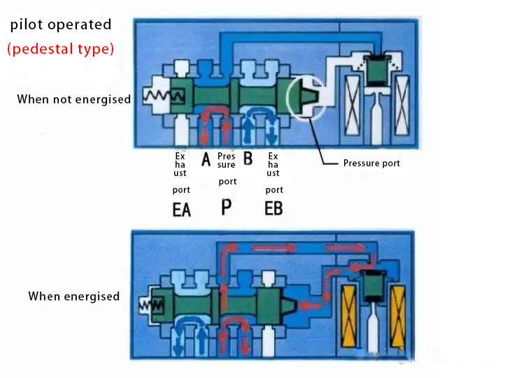
Pilot-operated solenoid valve: pilot-operated is through the coil to generate electromagnetic force under the action of the first open pilot valve to open the airway, so that air pressure to promote solenoid valve spool action to achieve the airway between the on and off. A very small electromagnetic force can change the valve path. This change in the valve path then achieves the purpose of altering the main spool position. As a result, the use of power is reduced.
Solenoid valve manual control principle
You need to pay attention to the solenoid valve manual button. This button is designed to facilitate debugging. You position it near the coil, and you can either press it or toggle it. Pressing the button causes the spool to toggle (either the direct-acting toggle solenoid valve main spool or the pilot-type toggle pilot spool), achieving the same effect as energizing the solenoid valve coil.
Contact Zhuo Yi Control Technology for the latest production technology!