
What are the characteristics of cartridge directional control valves?
We can combine hydraforce cartridge valve to form a variety of directional control valves.
check valve
As in Figures 1a and 1b, connecting the x-chamber to the A or B chamber makes a check valve. The connection method is different, and its conduction mode is also different. If we connect a two-position, three-way, liquid-operated directional valve to the control cover plate as shown in Figure 1c, we can form a liquid-controlled check valve.
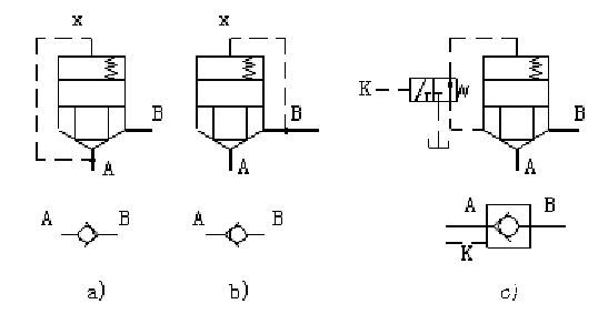
Figure 1 Cartridge Check Valves and Pilot Operated Check Valves
two-position two-way valve
Connect the two-position three-way valve as in Figures 2a and 2c to form a two-position two-way electro-hydraulic valve.
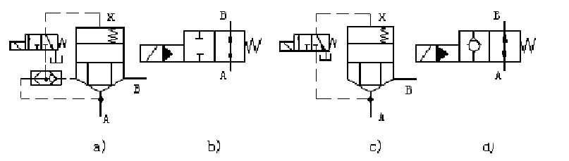
Figure 2 Cartridge type 2-position 2-way electro-hydraulic directional valves
two-position three-way valve
Connecting a two-position four-way valve as in Figure 3 can form a two-position three-way electro-hydraulic directional valve.
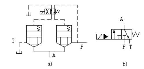
Figure 3 Cartridge type 2-position 3-way electro-hydraulic directional valve
two-position four-way valve
Connect the two-position four-way valve as in Figure 4 to form a two-position four-way electro-hydraulic directional valve.
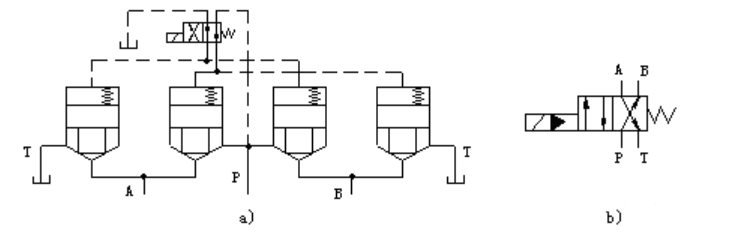
Figure 4 Cartridge type 2-position 4-way electro-hydraulic directional valve
O-type directional valves for three-position four-way valves
As shown in Figure 5 connect the three-position four-way valve directional valve and check valve, you can form a three-position four-way valve in the middle position for the O-type electro-hydraulic directional valve.
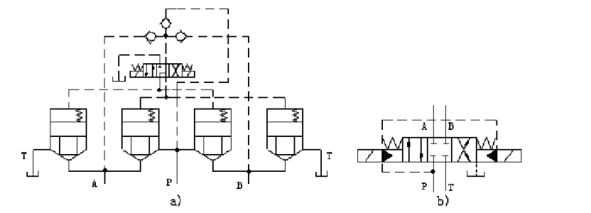
Figure 5 Cartridge type three-position four-way valve O-type electro-hydraulic directional valve
Multi-function four-way valves
As shown in Figure 6, the control of the solenoid valve is connected to the reversing valve to achieve a multi-function function. The functions of the pilot valve control state are shown in Table 1. The energised state of the solenoid is indicated by the symbol “+”; the de-energised state is indicated by “-“.
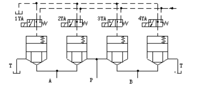
Figure 6 Cartridge type multifunctional four-way valve
Table 1 Slide Valve Functions Controlled by Pilot Valve

What are the features of cartridge pressure control valves?
Pressure control of the x-chamber of a hydraforce cartridge valve constitutes a pressure control valve.
relief or sequence valves
As shown in Figure 7a, when we connect a pilot regulator (relief valve) to the control cover of the pressure-type cartridge spool, the valve functions as a relief valve if we connect the outlet port to the oil tank. When we connect the outlet port to another working oil circuit, the valve functions as a sequence valve.

Figure 7 Cartridge pressure control valve
unloading valve
If we connect a two-position two-way directional valve as shown in Figure 7b, energizing the solenoid and connecting the outlet to the tank constitutes an unloading valve.
pressure reducing valve
The use of cartridge spool and relief valve connected as in Figure 7c constitutes a pressure reducing valve.
Hydraulic oil flows from P1 to P2, and we connect the outlet oil through the center damping hole on the spool, the cover plate, and the pilot valve. When the pressure reducing valve outlet pressure is small, not enough to open the pilot valve core, the main valve core on the damping holes only play the role of oil, so that the main valve core on the upper and lower two chambers of the liquid pressure is equal, and the upper chamber has a small spring effect, will make the main valve core in the lower end of the limit position, the pressure reducing valve core is wide open, do not reduce the role of pressure reduction; when the pressure increases to the pilot valve opening pressure, the pilot valve opens, the leakage of liquid flow back to the tank alone, the implementation of the External leakage.
During normal operation, the pressure reducing valve regulates the pressure. The outlet pressure, pilot valve relief pressure, and the main spool spring force achieve equilibrium. This balance maintains the throttling pressure reduction port at a certain value. When the outlet pressure increases, the damping hole flow resistance pressure drop causes an imbalance in the main spool force. This imbalance moves the spool upward and reduces the throttling pressure reduction port. As a result, the throttling pressure reduction effect is enhanced. Conversely, when the outlet pressure decreases, the spool moves downward. This action increases the throttling pressure reduction port and weakens the throttling pressure reduction effect. As a result, the system maintains the outlet pressure at the regulated value.
What are the characteristics of cartridge flow control valves?
Cartridge flow valves are also available as throttling valves and speed control valves.
throttle valve
In the direction of control cartridge valve cover installed spool travel regulator, adjust the spool and the valve body between the opening of the throttle port can control the flow area of the valve port, the role of the throttle valve, as shown in Figure 8a. In practice, we generally use the throttle valve cartridge spool in the structure of the sliding valve and open the throttling groove in the spool.
speed control valve
Cartridge-type throttle valves also have the same problem of unstable flow with load change. If we take measures to ensure a constant pressure difference between the inlet and outlet of the throttle valve, we can realize the function of a speed control valve. Such as Figure 8b connected pressure reducing valve and throttle valve plays such a role.
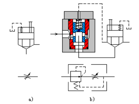
Figure 8 Cartridge Flow Control Valve
What should I pay attention to when designing and using hydraforce cartridge valve?
1) During operation, the hydraforce cartridge valve’s state is mainly determined by the oil pressure acting in the A, B, and X cavities, because the reset spring force is small. The pressures pA and pB are decided by the system or load. If external control is used (i.e., the control oil comes from other oil sources outside the working system), px is controllable; if internal control is used (i.e., the control oil comes from the working system itself), px will also be affected by the load pressure. Therefore, changes in load pressure and the effects of various shock pressures will inevitably interfere with the internally controlled control pressure.
Therefore, in designing the cartridge valve system, we must carefully analyze and calculate, gaining a clear understanding of the pressure changes in each branch throughout the cycle. We should pay particular attention to analyzing the shock pressure interference during the conversion process, especially in internal control methods. We must pay attention to the use of shuttle valves and check valves; otherwise, local inaccuracies or paralysis of the entire system will occur.
2) If several hydraforce cartridge valves share a common return or drain line, we should provide a separate return or drain line. This helps to avoid unintentional spool displacement caused by line pressure shocks.
3) We should pay attention to how the area ratio, opening pressure, opening speed, and sealing affect the valve’s performance.
4) Since independent control fluid resistances combine to form the hydraforce cartridge valve circuit, their action consistency cannot match the reliability of traditional hydraulic valves. For this reason, we should reasonably design the pilot oil circuit. We need to use shuttle valves, check valves, and other technical components to prevent the emergence of instantaneous road through. This is important to avoid system malfunctions or even paralysis.
5) We also refer to the valve block as the integrated block or channel block. It installs cartridge elements, a control cover plate, and connects external piping to the basic valve body. The valve block includes mounting holes for cartridge components, also known as insertion holes. It also has orifices for the main oil pipeline and control oil pipeline. Additionally, the valve block features a machining plane for mounting the control cover, a machining plane for mounting the external pipeline, and a mounting plane for the valve block. Installation and connection dimensions and requirements of two-way cartridge valve should be in accordance with national standards (GB2877). We can either select the valve block from the standard parts provided by the hydraforce cartridge valve manufacturer or design it ourselves according to our needs.
Contact Zhuo Yi Control Technology for the latest production technology!