
The importance of hydraforce manifold in the hydraulic system has been more and more people know, and its application range is more and more extensive, so is it good? Today, through the following introduction, we will learn about the hydraforce manifold.
The core component of the hydraulic valve is the hydraforce manifold, which plays an important role in controlling the direction, pressure and flow of the liquid flow in the hydraulic valve. The use of hydraulic valve block can not only simplify the design and installation of the hydraulic system, but also conducive to the integration and standardisation of the hydraulic system, which is conducive to reducing manufacturing costs, improve precision and reliability.
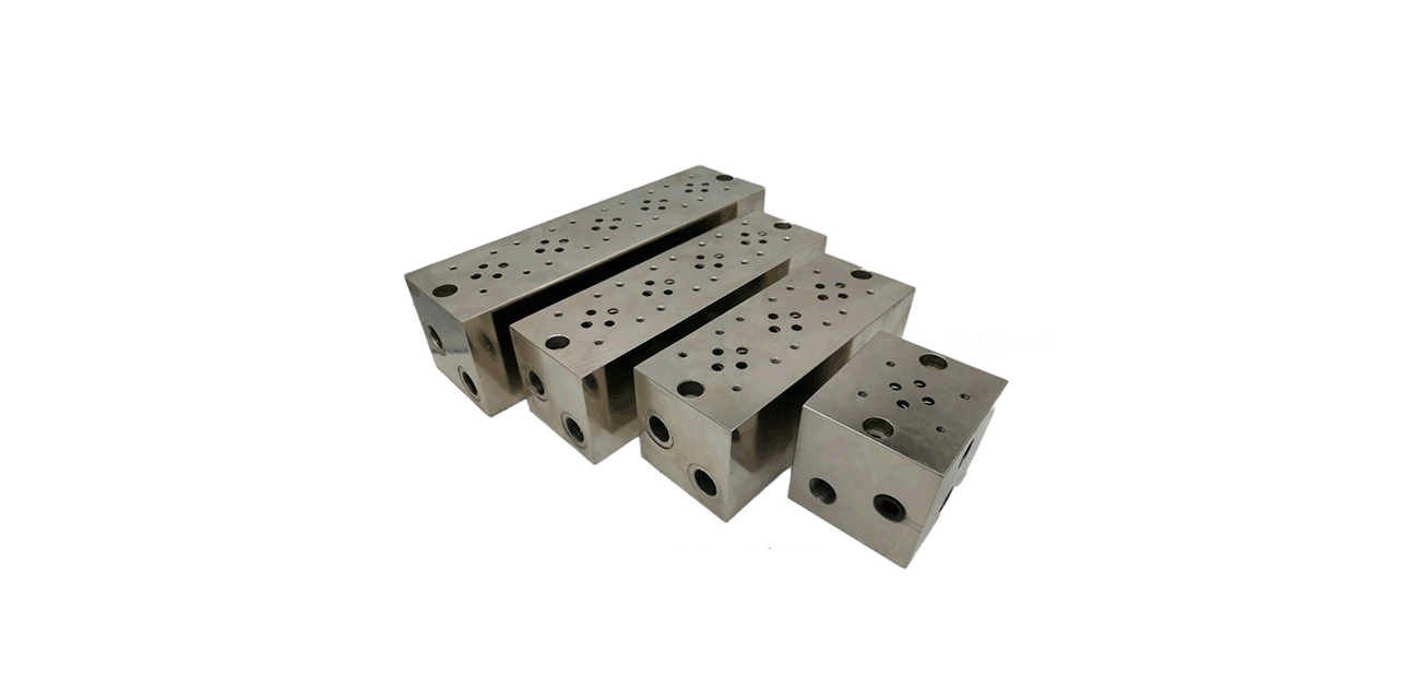
Hydraforce manufactures manifolds that come in various structures, including bar blocks, small plate blocks, cover plates, and cleats.
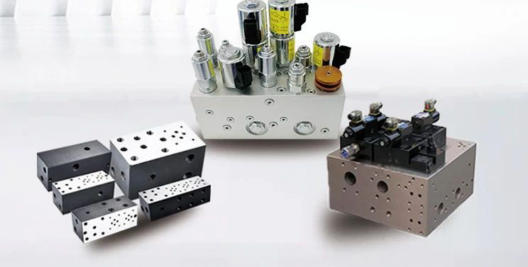
Hydraforce designs manifolds that fall into categories based on their use, including valve mounting base plates, pump valve blocks, logic valve blocks, stacked valve blocks, specialized valve blocks, manifold drains, and connecting blocks.
In the actual hydraulic system, the hydraforce manifold consists of the valve block body and various hydraulic valves, pipe fittings, accessories, and other components installed on it.

Composition of hydraforce manifold
body of the valve block
①The valve block body is the key component of the integrated hydraulic system. It not only carries other hydraulic components but also serves as the channel body for oil circuit connections.
② Valve block body are generally rectangular shape, the material is generally aluminium or malleable cast iron.
③ The valve block body includes hydraulic valve mounting holes, oil holes, connecting screw holes, and positioning pin holes. It also features public oil holes and connecting holes. These components ensure the correct connection of the apertures. However, they might sometimes interfere with the process of setting up holes.
④Simple valve block body has at least 40-60 holes, a little more complex on the hundreds of holes, these holes constitute a crisscross of holes system network.
⑤ The holes on the body of the valve block include light holes, step holes, threaded holes, and other forms. Generally, they are straight holes. These are easy to process on ordinary drilling machines and CNC machine tools.
hydraulic valve
Manufacturers generally produce hydraulic valves as standard parts, including various types such as plate valves, cartridge valves, and stacked valves. They mount these valves on the valve block body using connecting screws to achieve the control function of the hydraulic circuit.
Joint Fittings
①Couplings and fittings are used to connect external piping to the valve block.
② Various valves and the valve block body control the hydraulic cylinder and other actuators, as well as the oil inlet, oil return, and oil drain. They must connect to the external piping to achieve this.
Other accessories
Includes accessories such as pipe connection flanges, process hole plugs, and oil line seals.
Attention to the design of hydraforce manifold
You should select the interface elements between the block and the external pipework (pipe connections or flanges) in advance. Consider their external dimensions, as these will influence the determination of the overall dimensions of the block.
The maximum side length of the valve block should not exceed 600mm. Additionally, the number of two-way cartridge valve inserts included should not exceed 8. When you use more than 8 inserts, decompose them into several valve blocks. Connect the valve blocks with each other using bolts. Seal the connection apertures at the bonding surfaces with O-rings. This will assemble the entire valve block group.
- All external oil ports and inspection ports of the valve block should have oil port markings. These markings should be consistent with the corresponding markings on the hydraulic schematic diagram. The steel mark should be no less than 6mm from the orifice, provided it does not affect the sealing performance of the O-ring.
- For the larger mass of the block must have lifting screw port (preferably placed on the top surface, can also be placed on the side, in order to the block assembly after lifting process does not flip as the principle) for the installation of lifting ring screw (to meet the standard GB825-88).
- Considering the fixation of the valve block, the bottom of the valve block should be set up with mounting bolt holes (small valve blocks can be through holes, large valve blocks are blind holes; the number of holes is generally 4, large valve blocks are 6 or even more, the holes are evenly distributed and follow the relevant design standards), the valve block may be mounted on the top of the tank, the outlet of the pump, the workbench and the hydraulic cylinders, which is to be determined in accordance with the actual situation, and it can be mounted directly or with the welding of brackets with profiles for mounting.
- The external oil port of the main stage orifice generally connects with a flange. For smaller oil ports with a through diameter of 25mm or less, you can also use a threaded connection. The external oil port of the pilot orifice is suitable for a threaded connection.
- You should block process orifices using removable means such as screw plug flanges. This approach allows for cleaning, washing, and inspection of the orifices. When the location does not allow, you can use the ball-up plug to seal apertures with a diameter of not more than 12mm.
- When valve block entropy installs conventional industrial solenoid valves or stack valves of 6, 10, 16, or 25 through diameters, the connecting bolts shall have a rectangular performance of not less than grade 12.9.
- You should install necessary test ports on the main stage orifices and main pilot orifices. This will allow you to check the working parameters of the hydraulic circuit and to discharge faults. You should install the detection port with a quick-connect function for the pressure measurement connector.
When the pipeline size differs significantly from the size of the internal orifice of the valve block, consider using a reducer joint. This approach helps accommodate the size difference between the pipeline and the valve block orifice.
Should be reserved in the valve block of the conspicuous location of the nameplate installation position.
Contact Zhuo Yi Control Technology for the latest production technology!


