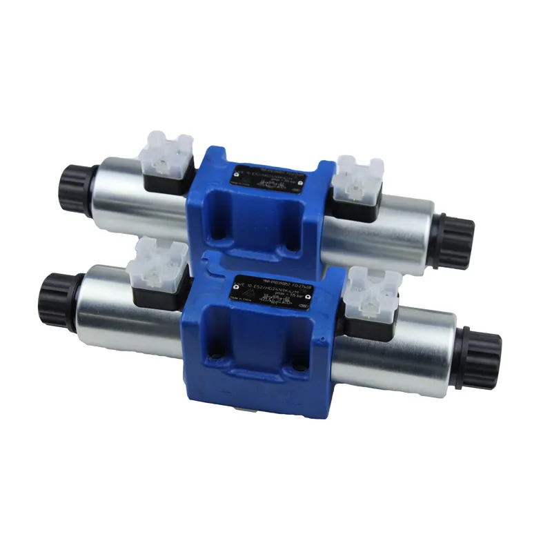
International Standard 2-way Cartridge Valve consist of ISO CV 7368 mounting holes and slide-in inserts. They differ from plate-type valve elements in that they have their own circuitry, which is unique to their mounting and assembly in the control valve block. They are briefly described below:
(1) Basic elements of ISO CV control valve blocks – IS0 7368/DIN 24342/GB/T 2877.2 Mounting holes The dimensions and requirements for the mounting hole connections of 2-way cartridge valves have been provided by a national standard, which is GB/T 2877.2-2021. Therefore, designers can refer to this standard when creating 2-way cartridge valve blocks. Figure 26-343 provides relevant details.
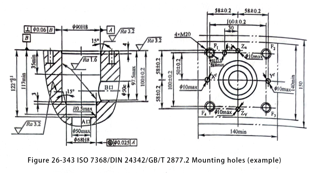
With regard to the standard for mounting holes IS0 7368 CV (see Table 26-148) the current new revised version of the standard should be followed.

(2) The design combination of basic forms for power level plug-in valve blocks includes various types. Valve block bodies are categorized based on different structural types and features. They are divided into overall valve blocks, combined valve blocks, and integrated valve blocks.
Design an integral valve block for a single device to provide centralized control functions. It can control either a single functional circuit or multiple functional circuits.
Combined valve block has the function of controlling an independent circuit (such as single-acting or double-acting actuator control circuit, etc.). Its installation and connection adopts the way of single element, such as plate type, pipe type, flange connection, etc..
Integrated valve block usually consists of several single function blocks with certain control functions, using laminar connection structure or other connection structure for superposition or block connection. It is mainly used for more than one circuit of the more complex hydraulic system for integrated control.
The integrated valve block typically features structures such as the three-way block body and the four-way block body. Figures provide the structural arrangement of the three-way block. Additional figures illustrate the arrangement of the four-way block. 26-344 and 26-345, respectively. It can be used as a reference when designing the valve block.

The functional valve block, based on the basic power circuit in Figure 26-336, is the foundation in the ISO CV control valve block design portfolio. A certain topological relationship exists between the mounting hole elements in the body of the functional valve block. This relationship involves the connections and linkages between the major internal flow paths P, A, B, and T. The topological relationship between the mounting holes is shown in Figure 26-344 and Figure 26-345. Figure 26-344 and Figure 26-345 show schematic diagrams of several typical layout combinations. These diagrams feature a basic power loop valve block with two mounting holes in an ISO CV. You can compare these layouts to the four basic power loops and positional functions in Figure 26-336.
Figure 26-346 shows an illustration of a typical control valve block layout combination. It features two basic power circuit valve blocks with four mounting holes. These blocks form two controlled chambers in ISO CV.
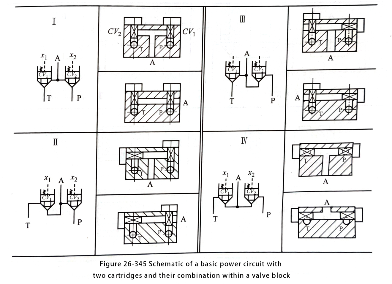
Figure 26-346 illustrates the four basic power circuits and position combinations. The diagram also shows the connection and connectivity relationships between the internal mounting hole (CV*) orifices and the main lines P, A, B, and T. Additionally, it features a typical four-way circuit seated valve main stage and main line combination.
Figures 26-345 and 26-346 show the connections and features between the internal mounting orifices (CV*) and the main piping P, A, B, and T in the combination of the two basic power circuits I, II, III, and IV.
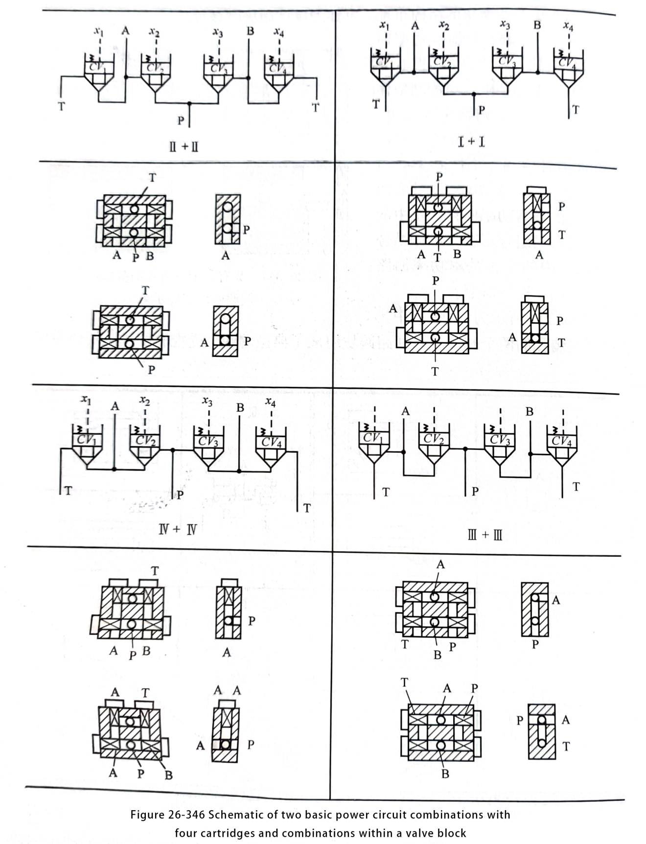
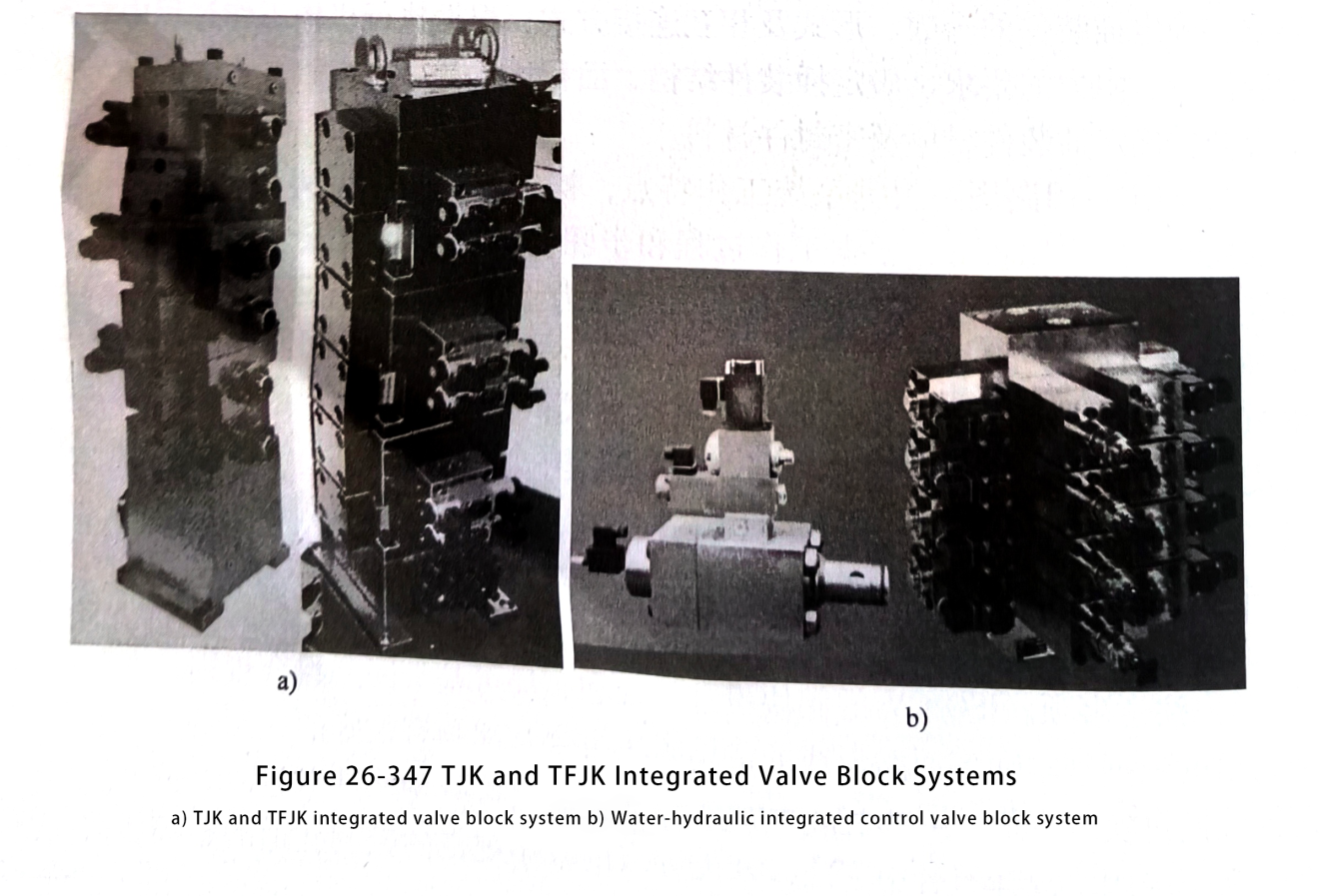
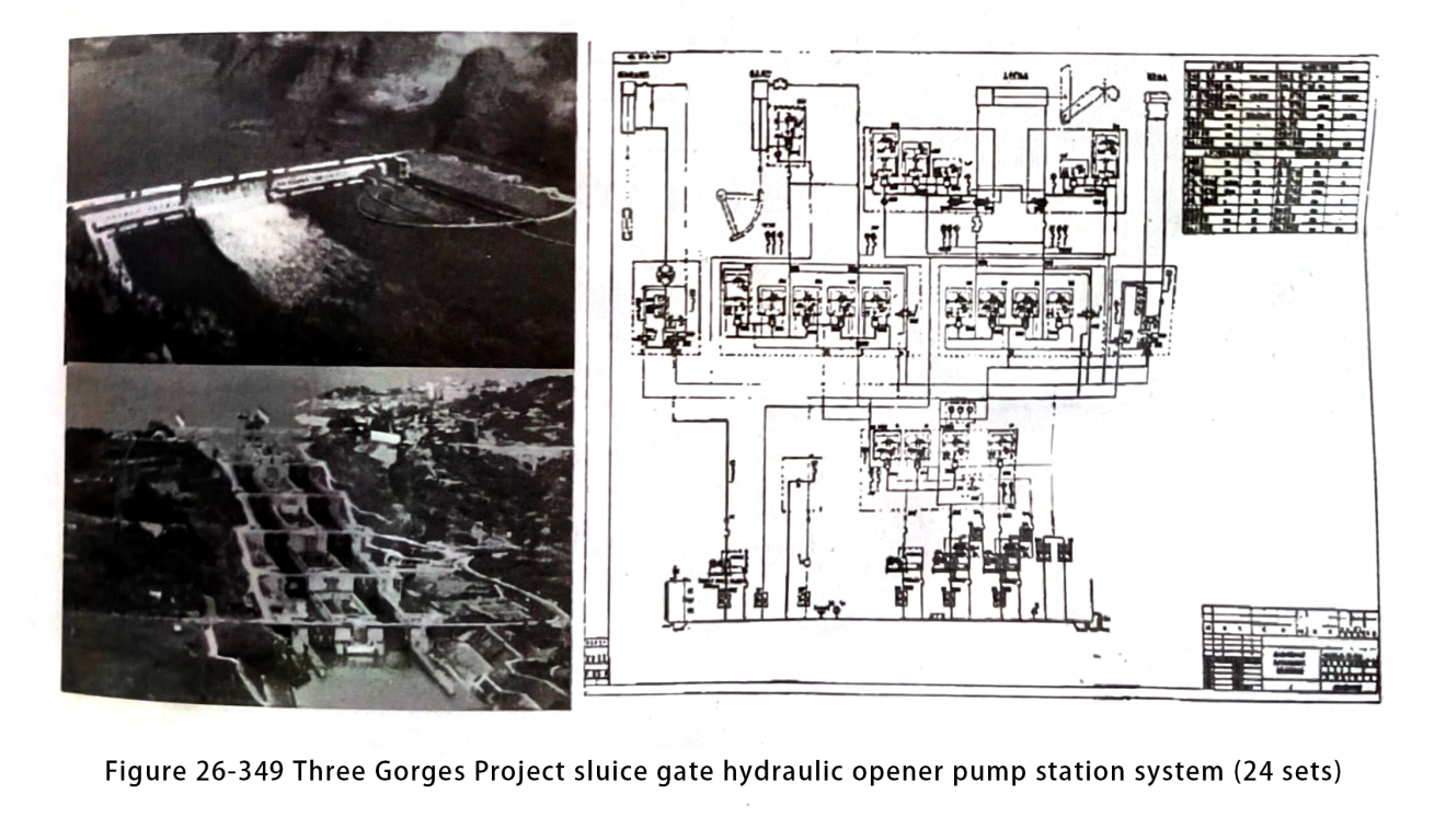
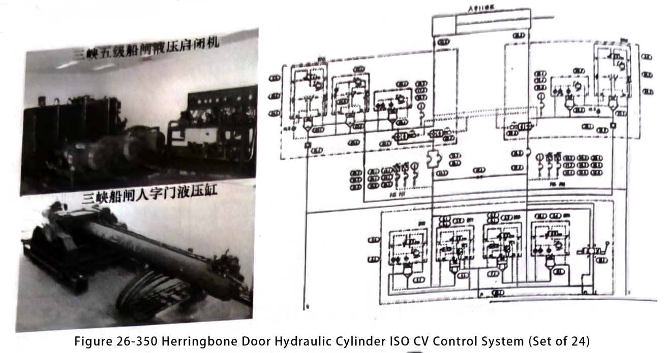
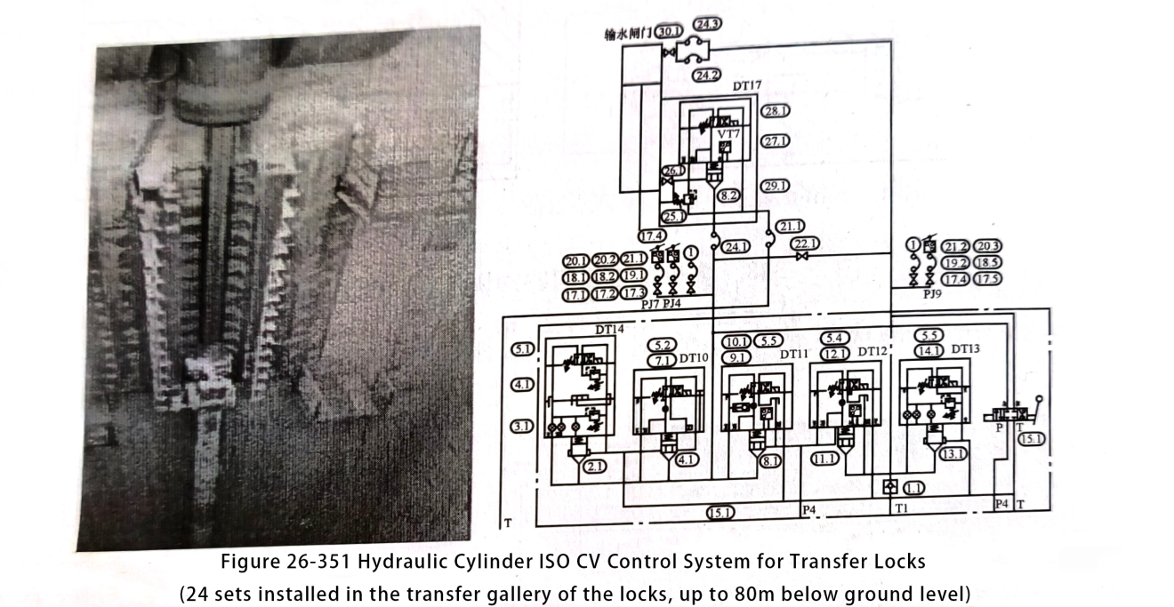
The internal structural layout of the valve block is different from that of the other combinations (groupings) in the form of characteristic forms. In fact, they can roughly accommodate most of the common combinations in four-way circuits. For example, among the large number of typical combinations at home and abroad at the early stage of the formation of ISO CV, the TJK and TFJK 1S0 CV integrated systems developed and successfully applied by China and the basic control loops in the Three Gorges Project of the Yangtze River are all in accordance with and adopt some of the combinations contained therein.
(3) Valve block design combination of some important rules
1) Selection principle. The biggest advantage of 2-way cartridge valves is high pressure, large flow, large diameter, so 2-way cartridge valve product line is constantly expanding its diameter record, improve the pressure rating.
At the same time, 2-way cartridge valves offer advantages over common tube-connected or plate-connected slide-type directional, pressure or flow control valves in a variety of ways, including greater system design flexibility, lower set-up costs, smaller external dimensions, better performance and control, improved reliability, higher pressure capability, higher operating efficiency, elimination of external leakage and reduction of internal leakage, greater resistance to contamination, faster cycle times, lower noise levels, etc.
However, despite the many functional advantages of two-way cartridge valves, they are not as easy and convenient to use as existing plate valves. Threaded cartridge valves are more suitable for small flows. Therefore, when designing a hydraulic system, it is often most economically rational to select a combination of threaded cartridge valves, cover-type cartridge valves, and common sliding valve-type valves. Install all of these valves in the common block of the oil circuit. Leverage their strengths and complement their shortcomings.
As the cartridge valve control technology is based on the independent control of individual resistance, so the selection of cartridge valves, in addition to the general selection of hydraulic valves principles, there are some special features.
① First, determine the basic requirements and parameters of the system. Assess whether two-way cartridge valves are applicable based on the system characteristics and valve features. Identify the requirements for actuators, including parameters such as force, torque, pressure, displacement, and speed, along with the control methods. Define the work processes of various actuators and their corresponding pressure, direction, and flow. Finally, determine the required transitions between the different work processes of the actuators.Determine the requirements for control safety.
② Determine the specific type of cartridge valve: according to the requirements of the actuator working process of the oil discharge cavity resistance control, determine the number of cartridges, forms and ways of connecting with each other; according to the requirements of the actuator working process of the oil discharge cavity flow, resistance, to determine the structure of the cartridge, the ratio of the area, the opening pressure, buffer function, etc.; according to the medium of the system to determine the material of the cartridge and the sealing material.
③ The preliminary main circuit diagram is based on the working characteristics of the system. The initial pilot control scheme includes external control, internal control, and pressure comparison. Based on the work process and steps, we determine the pilot direction of the control cover, such as cover function, and decide whether to use a slide valve or seat valve for pilot control. Bosch Rexroth series stipulates using NG6 pilot valves for diameters between 16 and 63mm. Similarly, the 704 standard specifies using NG6 pilot valves for diameters between 16 and 40mm.
First, determine the diameter of the pilot valve, such as NG6 or NG50, and choose the form of voltage and control method. Next, based on the working process, assess the pressure and flow requirements for each discharge chamber to define the functions of pressure and flow control covers, such as proportionality, decompression, sequencing, and unloading. Finally, specify details like damping, composite control, leakage control, and pressure selection forms.
④ Finalise all components:First, determine the plug and control cover type based on the preliminary assessment. Next, perform overall cross-validation. Finally, make the appropriate changes to finalize the component type specifications.
2) Note: The design combination and layout of valve blocks for ISO CV can be based on the rules of circuit combination, especially the common combinations of valve blocks based on the basic power circuits listed above, which are all of good reference value. Make full use of the cartridge valve can achieve multi-function, multiple composite function characteristics, minimise the number of components.
Power level valve block design combinations, but also involves the layout of the pilot level of the smaller size of the control orifice, need to meet the function of the pilot control and structure under the premise of the requirements of the flexible use. Pay attention to the role of damping, which greatly impacts the entire system’s steady state and transient characteristics. Be particularly careful with the transition state requirements. Generally, finalize the damping only after the system commissioning is completed.
The design combination of the power level valve block also relates to the overall valve block and system assembly. It includes the installation requirements and the configuration requirements for various accessories. Pay attention to the reliability of the control. In particular, ensure the pressure selector element in the internal control is reliable. This helps avoid pressure interference in the relevant circuits.
The power level valve block design combination must meet basic requirements such as functionality, installation, ease of use, and maintenance. It should also follow the lightweight design concept.
3) common failures. Common troubleshooting methods for universal hydraulic valves are also applicable to cartridge valves, such as unreliable commutation, unstable pressure, etc..
As most of the cartridge using the seat valve form that is line seal, a few use line seal and face seal combination, so when there is unreliable commutation or pressure regulation failure should be the first to check the cartridge spool, set whether the jamming, pilot control directional valve commutation is normal.
Pay special attention to the control pressure when the cartridge directional valve commutation is unreliable. Verify if the selected components meet the pressure requirements. Ensure it meets the requirements, and verify the reliability of the pressure selection components, such as the shuttle valve or hydraulic ball valve. Additionally, check whether the pressure of the relevant oil circuit produces interference.
If the cartridge pressure valve exhibits pressure instability or vibration, inspect the precision and shape tolerance of the cartridge spool and sleeve to ensure they meet the requirements. Also, verify the stability of the pilot pressure control element.
Should the system transition process fail to meet the requirements, examine whether the size of the damping hole is reasonable. Additionally, check if the damper is off.
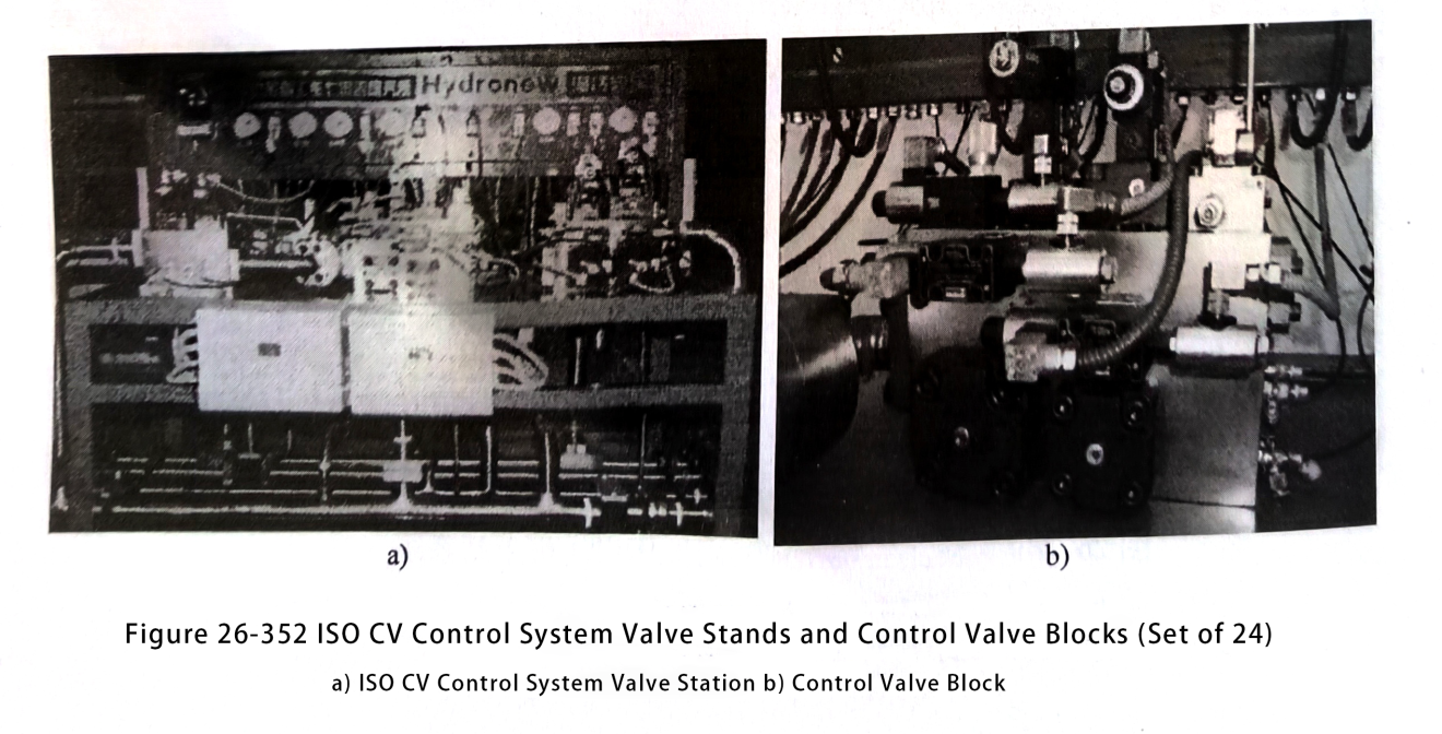
(4) Typical Functional Valve Block Application Examples Fig. 26-347~Fig. 26-352 shows the application examples of typical functional valve blocks.

Contact Zhuo Yi Control Technology for the latest production technology!