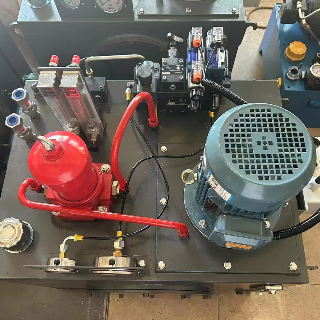
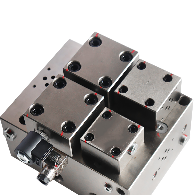
With the progress of hydraulic technology and the development of hydraulic components, more and more of the various types of hydraulic components installed in the hydraulic solenoid valve block composed of integrated valve group to achieve a certain function, such a configuration relative to the pipe connection system has the following advantages:
1)Adopting plane seal, easy to install and not easy to leak;
2)Compact structure, occupies little space;
3)Good workmanship, easy to achieve mass production;
4)Easy installation and maintenance;
5) Convenient to achieve standardised design.

Design of hydraulic valve integration unit
The design of the hydraulic valve integration device should take into account both practical and aesthetic factors. Hydraulic valve integrated device is the core of the hydraulic solenoid valve block, the valve block design is reasonable on the system’s manufacturing, installation and performance has a great impact.
Selection of Hydraulic Solenoid Valve Block Material
The choice of material determines the pressure resistance level of the valve block, while the choice of material determines the manufacturing cost of the valve block, under the condition of meeting the pressure requirements, try to use low-cost materials to save costs. Generally follow the following principles:
When the working pressure p <6.3 MPa, using cast iron HT20-40 for manufacturing hydraulic solenoid valve blocks allows for mass production, reduces labor hours, and improves efficiency, especially for standardized valve blocks.
When 6.3 MPa ≤ p <21 MPa, hydraulic solenoid valve block can choose aluminium alloy forgings, 20 Q 235 forged steel.
When p≥21 MPa, hydraulic solenoid valve block can choose 35 forging steel. After forging and tempering treatment to HB 200-240 before processing.
Design of the hydraulic solenoid valve block
Before designing the valve block, first of all, read and understand the system schematic diagram, figure out the role of each component in the system, and familiarise yourself with the external dimensions and interface dimensions of each component in comparison with the samples. When designing the connection orifice of the valve block, the following matters need to be noted:
1)The internal channel of the valve block should be as simple as possible to minimise deep holes and elongated holes.
2) For components with horizontal or vertical installation requirements, to ensure that their installation meets the requirements of use;.
3) Minimise process holes, if you do need process holes, you can use the process holes to install pressure gauges, pressure sensors and other detection components.
4) The work requires frequent adjustment of the components, try to install in a position that is easy to adjust;
5) For cross-linked holes, ensure that you reach the general depth of the through-hole centerline. If the hole is too deep, it may create a dead zone in the oil circuit. For the holes in the valve block, use process holes to install pressure gauges, pressure sensors, and other detection components.
7) If the processing capacity of the manufacturer – general, try to use the flange connection, you can avoid the thread processing deviation caused by oil leakage or oil seepage phenomenon.
8) The wall thickness between the oil holes can be calculated using the formula for calculating the wall thickness of the oil pipe.
9) The oil holes on the valve block, as far as possible, divided into several layers, so as to facilitate the design, while not easy to make mistakes.
10) The components on the valve block, try to use standard parts, conducive to the maintenance of the later stage.
11)In the process of valve block design, first ensure the function, function design and then consider further optimisation, whether it is possible to reduce the size of the valve block to save costs.

Processing of hydraulic valve integration unit
The hydraulic solenoid valve block is the main part that needs processing in the hydraulic valve integrated device. The manufacturing unit should develop a reasonable machining process based on the drawings.
The processing process needs to pay attention to the following matters:
1) Ensure that the material of the valve block has no internal interlayers, trachoma, or other defects. For critical valve blocks, carry out flaw detection and inspection. For cast iron parts and forgings, perform aging treatment or annealing treatment before processing.
2) Valve block processing, must ensure that its surface roughness, its surface shall not have scratches, pitting and other defects, otherwise it is easy to cause leakage;
3) After the processing of the valve block is completed, all the oil passages need to be deburred.
Assembly of hydraulic valve integration unit
Assembly is carried out after all parts have been machined. The assembly of the hydraulic valve integration unit requires the following attention:
1) Cleaning: Before assembly, thoroughly clean the valve block. After cleaning, use an endoscope to check that you do not leave any iron filings or other debris in the orifices.
2) Assembly: Before assembly, confirm the model of all components. For valve blocks equipped with valves of the same type but different pressure levels and shapes, ensure that you install each component in the correct position;
3) It is best to use a torque spanner when assembling, if there is no torque spanner conditions, for screws smaller than M10, the torque when tightening can not be too large otherwise it is easy to strain the threads.
Commissioning of hydraulic valve integration unit
Hydraulic solenoid valve block for debugging before the need for cyclic flushing, the purpose of which is to flush the valve block internal flushing to ensure that the normal operation of the components, flushing the general system pressure of 5 MPa, flushing process will be the throttle valve opening to the maximum, the pressure valve regulating screws completely tightened. Valve device commissioning is divided into two parts, one is the pressure test, the other part is the function test.
1) pressure test: test pressure based on the system working pressure to determine the working pressure, that is, the working pressure is less than 16 MPa, the test pressure for the working pressure of 1.5 times; the working pressure is greater than 16 MPa less than 31.5 MPa, the test pressure for the working pressure of 1.25 times; the working pressure is greater than 31.5 MPa, the test pressure for the working pressure of 1.1.5 times.
In the pressure resistance test, gradually increase the pressure in steps, generally 5 MPa per level. At each level, observe for 5 minutes to check for abnormalities. If no abnormalities are observed, adjust to the next level. Once you reach the test pressure, observe for 10 minutes. During the pressure test, if you find any leakage, step down and shut down to investigate the cause. After troubleshooting, re-examine the test.
2) Functional test: according to the system schematic diagram, the valve device working oil port connected to the test hydraulic cylinder, the reversing valve for reversal, to determine whether the circuit is correct, the pressure valve for pressure regulation, to determine whether the pressure adjustment is normal. Test each action several times, and if you find any problems during the test, identify and solve the issues.
3) After completing the test of the hydraulic valve integrated device, clean up the residual oil. Then, seal all external oil ports with pipe caps. This ensures that the inside of the hydraulic valve integrated device remains uncontaminated.
Hydraulic practitioners will encounter problems related to the hydraulic valve integrated device. Through practice and by summarizing their experiences, they can make the hydraulic valve integrated device design more reasonable. This approach makes the maintenance and use of hydraulic systems more convenient and reliable.
Contact Zhuo Yi Control Technology for the latest production technology!