
We widely use hydraulic cartridge valve in hydraulic machinery. In the manufacture and maintenance of hydraulic systems, we cannot separate the installation and removal of hydraulic cartridge valve. To ensure the normal operation of the hydraulic system, we must master the correct installation and removal methods.
How do I install a 2-way hydraulic cartridge valve?
The two-way cartridge valve generally consists of cartridge assembly, pilot control valve, control cover plate and integrated valve block, etc. Its typical structure is shown in Figure 3-91.
Cartridge assembly 1 consists of spool, sleeve, spring and fixed sealing assembly, etc. It can be cone valve type structure or slide valve type structure, and its main function is to control the on/off of the main oil circuit, the pressure level and the flow rate.
We mount Pilot control valve 2 on the control cover plate (or integrated valve block) on the cartridge assembly 1 to control the small aperture control valve. This mainly includes DN6 and DN10 solenoid slide valves, solenoid ball valves, proportional valves, adjustable dampers, buffers, and liquid-controlled pilot valves. When the main plug-in aperture is large, we use a smaller aperture for two-stage control to improve the dynamic characteristics of the cartridge.
The cover plate body, throttle screw plug, pilot control element, and other accessories compose the control cover plate 3. It primarily fixes the cartridge assembly 1, installs the pilot control valve 2, and communicates the control oil circuit in the valve block. We can divide the control cover plate into three categories: direction control cover plate, pressure control cover plate, and flow control cover plate. When the control cover plate has more than two kinds of functions, we call it a composite control cover plate.
The integrated valve block 4 mounts the cartridge assembly, control cover plate, and other control valves to connect the main oil circuit. Two way cartridge valve mounting hole connection size standard for ISO7368, this standard is basically according to the German DIN24342 standard, China’s national standard GB/T 2877 – 2007.
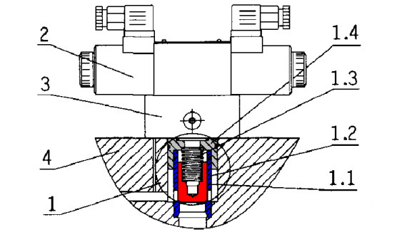
1. cartridge assembly 2. pilot control valve 3. control cover plate 4. integrated valve block
1.1 spool 1.2 sleeve 1.3 spring 1.4 fixed seal assembly
Figure 3-91 Typical structure of two-way hydraulic cartridge valve
The structure of two-way cartridge valve has various forms, as shown in Figure 3-92. There are mainly REXROTH-type structure (a), PARKER-type structure (b), VICKERS-type structure (c) 3 kinds, these 3 kinds of structure have their own advantages and disadvantages.
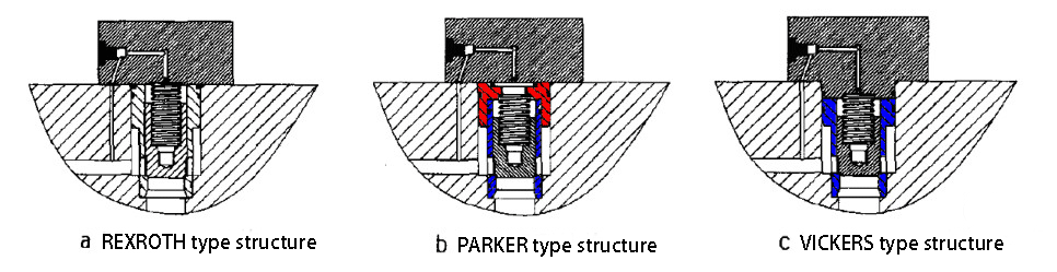
Figure 3-92 Hydraulic Cartridge Valve Construction Forms
The following should be done before installing a two-way cartridge valve:
(1) Check the dimensions of the socket, such as the inside diameter, the depth of each step, and the chamfer.
(2) Check the roughness of the jacks. Remove angles and burrs at the chamfers and intersections to avoid damaging the seals of the cartridge assembly.
(3) Check the concentricity of the jack with a special gage.
(4) Check the type of each component and each seal, disassemble, clean, replace, and perform performance tests if necessary.
(5) Clean the block components.
When you install the 2-way cartridge valve, apply grease or oil to the jack and the outer ring of the cartridge assembly (especially at the sealing ring). Then, place the cartridge assembly into the jack, tap it into the jack with a rubber mallet, or press it into the jack with the cover screws. Secure the control cover with the socket head cap screws, and finally, install the pilot control valve. The tightening torque of the socket head cap screws is shown in Table 3-13.
The following points should be observed when installing the 2-way cartridge valve:
(1) When installing the cartridge assembly, ensure you do not miss the spring. Also, make sure the seal and retaining ring are not cut during assembly.
(2) When you install the control cover plate, align the oil ports or locating pins carefully. Use high-strength screws (Grade 10.9 or Grade 12.9) for the set screws.
(3) If the spring of the cartridge assembly is particularly hard, install the cover plate with a long screw first. Then, replace it with a short screw when it is pressed to the proper position.
Table 3-13 Tightening torque table for fixing screws for control cover plate
| No. | Diameter of control cover/mm | Hexagon socket head cap screws specifications | Tightening torque/Nm |
| 1 | 16 | M8 | 32 |
| 2 | 25 | M12 | 110 |
| 3 | 32 | M16 | 270 |
| 4 | 40 | M20 | 520 |
| 5 | 50 | M20 | 520 |
| 6 | 63 | M30 | 1800 |
| 7 | 80 | M24 | 900 |
| 8 | 100 | M30 | 1800 |
| 9 | 125 | M36 | 3100 |
| 10 | 160 | M42 | 5000 |
How do I install a threaded cartridge valve?
We install threaded cartridge valves by screwing the screw strand directly into the socket of the valve block, making installation and disassembly simple and quick.
Figure 3-93 shows the typical structure of a screw-in cartridge valve. The structure consists of a valve sleeve, spool, valve body, seals, and control parts, including the spring seat, spring, adjusting screw, magnetic body, solenoid coil, and spring pads. Threaded cartridge valves have two-way, three-way, four-way and other types; directional valves have check valves, liquid-controlled check valves, shuttle valves, hydraulic directional valves, manual directional valves, solenoid valve, solenoid valve, electromagnetic ball valves, etc.; pressure valves have relief valves, pressure reducing valves, sequential valves, counterbalance valves, pressure relief valves, load-sensitive valves, etc.; flow valves have throttle valves, speed regulating valves, shunt collection valves, priority valves and so on.
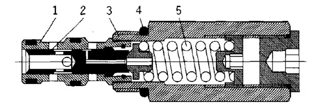
1 valve sleeve 2. spool 3. valve body 4. seal 5. control components
Figure 3-93 Typical Structure of a Threaded Cartridge Valve
Perform the same work before installing a threaded cartridge valve as when installing a two-way cartridge valve.
When you install threaded cartridge valves, first apply grease or oil to the socket and the outer ring of the valve sleeve (especially at the sealing ring). Next, insert the threaded cartridge valve into the socket and screw it in using a torque spanner (or open-end spanner). The table in Table 3-14 shows the required tightening torque for commonly used threaded cartridge valves.
Table 3-14 Required tightening torque for commonly used threaded cartridge valves
| No. | Threaded cartridge valve bore/mm | Tightening torque/Nm |
| 1 | 4 | 10~15 |
| 2 | 8 | 34~45 |
| 3 | 10 | 47~65 |
| 4 | 12 | 81~122 |
| 5 | 16 | 108~190 |
| 6 | 20 | 150~271 |
The following points should be noted when installing threaded cartridge valves:
(1) Install threaded cartridge valves in a way that avoids cutting the seals and retaining rings during assembly.
(2) Since the threaded cartridge valves in the valve group are relatively dense, install them in sequence in one direction.
(3) When installing solenoid valves, first remove the solenoid if you have limited space. Install the valve body first, and then reinstall the solenoid afterward.
How do I disassemble a 2-way cartridge valve?
Disassemble the two-way cartridge valve in the order of pilot control valve → control cover → cartridge assembly. The following mainly explains the disassembly method of the cartridge assembly of the two-way cartridge valve.
Referring to Figure 3-94, follow this disassembly sequence for the cartridge assembly of the two-way cartridge valve: first remove the fixed seal assembly, then the spring, followed by the spool, and finally the sleeve. The specific steps are as follows:
(1) Remove the fixed sealing assembly (threaded in the centre) with a pin puller, sometimes the fixed sealing assembly will pop out by itself under the action of spring force.
(2) Remove the spring.
(3)To take out the spool, use tools if the spool is stuck. Some spools have process screw holes at the bottom; you can use a pin puller to disassemble them. If the spool lacks process screw holes, use the special tool shown in Figure 3-94. Insert the opening of the expansion sleeve and the inverted cone expander into the spool’s bore. Rotate the T-shaped screw to expand the sleeve through the inverted cone expander and tighten the spool. Then, tap the upper end of the T-screw with an impact casing to pull out the spool.
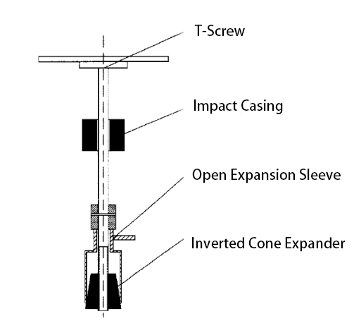
Figure 3-94 two-way cartridge valve cartridge assembly spool disassembly tool
(4) You can disassemble a 16~25mm diameter spool using the simple tool shown in Figure 3-95. To disassemble a 25mm diameter spool, use the tool shown in Figure 3-96. Insert the pendulum inclined rotary rod into the inner hole of the spool. When the inclined rod enters the runner hole of the spool, pull the tool upward and swing the inclined rod upward. Hook the inclined rod on the two ends of the spool to the runner hole of the spool. Pad the ends of the stretcher with padding, and then turn the nut with a spanner to pull out the spool. You can pull out the valve sleeve by turning the nut with a spanner.
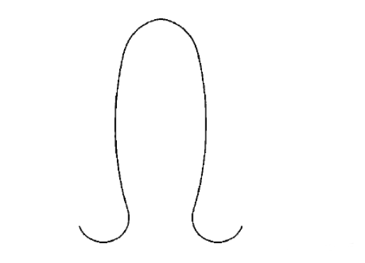
Figure 3-95 Simple Removal Tool for Cartridge Assembly Bushings of 2-Way Cartridge Valves
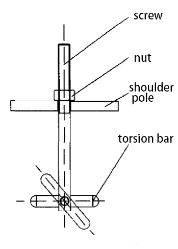
Figure 3-96 Removal tool for cartridge assembly sleeve of 2-way cartridge valve
The following points should be noted when disassembling the two-way cartridge valve:
(1) Remove pressure and power before removing wires.
(2) When disassembling the control cover, mark its original position if the valve block lacks a locating pin hole to avoid mistakes.
(3) Be careful not to scratch the inner hole of the valve cover and the socket of the valve block during disassembly.
How do I disassemble a threaded cartridge valve?
Threaded cartridge valves are simple to disassemble by turning them out with a spanner. When we need to disassemble the threaded cartridge valve, first remove the sealing ring and the retaining ring. Then, use the suitable open sleeve (shown in Figure 3-97) to fit onto the threaded cartridge valve sleeve (shown in Figure 3-93). Clamp the assembly on the three-jawed chuck to rotate the valve body and push out the valve spool. If you cannot rotate the valve body, place the valve in diesel fuel to heat it up to 190°C, and then disassemble it.
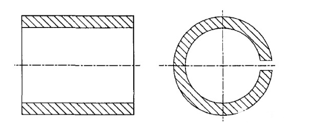
Figure 3-97 Removal Tool for Threaded Cartridge Valves
When you disassemble the threaded cartridge valve, you should note the following points:
(1) Remove the pressure and disconnect the power before removing the wires.
(2) In a more compact position, disassemble the components in a specific sequence and direction. Start by removing those with solenoids first.
(3) For threaded cartridge valves that we need to disassemble, apply medium-strength removable thread locker to the threads during assembly, and use a suitable cotter sleeve to screw it onto a three-jaw chuck.
Contact Zhuo Yi Control Technology for the latest production technology!