
1.Function
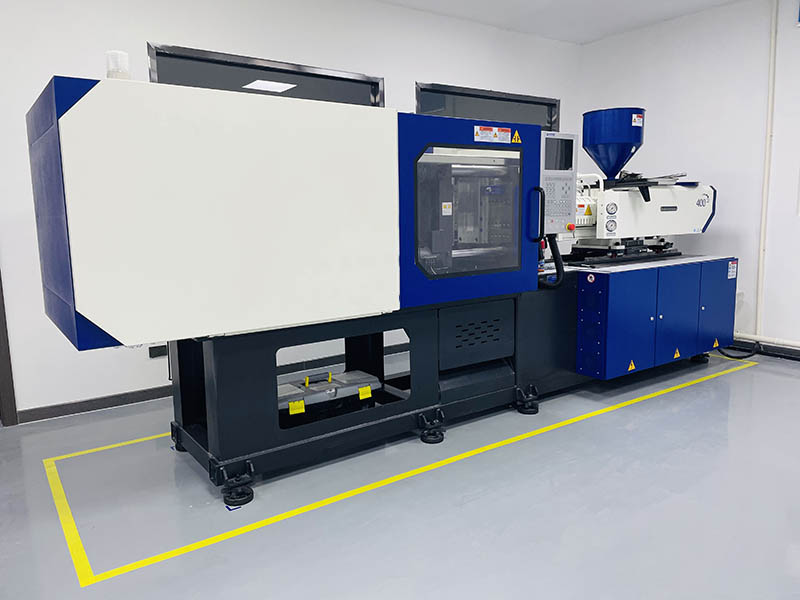
Plastic injection molding machine is a machine that heats and melts the granular plastic, injects the molten plastic into the pre-consolidated metal mold with high pressure, cools and solidifies, and then opens the mold to take out the product. The hydraulic circuit of the injection molding machine consists of a closing circuit to close the mold and an injection circuit to inject a certain amount of molten plastic into the mold. In addition, there is an oil contamination control circuit and an oil temperature control circuit.
2. Process and hydraulic circuit
The working cycle of the injection molding machine generally includes five steps: closing the mold, injecting and holding pressure, measuring, opening the mold, and removing the products.

Control Function
The control functions include sequential control to actuate multiple hydraulic valves for step changeover and process control to maintain predetermined conditions. Operators use electromagnetic proportional flow control valves and electromagnetic proportional relief valves for process control. Therefore, their performance is highly related to the quality of products.
Mold opening and closing steps:
Directional valves A2, A3 and A4 are neutral. If at this time the electromagnetic flow control valve FC for the appropriate degree of opening, the pressure oil from the large pump PF2 and the pressure oil from the small pump PF1 convergence to determine the variable speed of the high-speed zone. Mold opening and closing are selected using the switching direction of A1. The low speed zone is determined by the amount of PF1 only.
Injecting step: Close the mold only with the oil pressure of PF1, and at the same time, switch A3 to lead the pressure oil output from PF2 to the back cavity of the injection cylinder through FC and A3, so that the screw advances to the left side of the figure, and the molten plastic is injected into the mold cavity through the nozzle at the front end of the screw.

The molten plastic is injected into the mold cavity through the nozzle at the front of the screw. During injection, operators change the input signal of FC to control the speed of screw advancement. In the measuring step, operators determine the quantity of molten plastic to inject into the mold. The hydraulic motor rotates the screw and pushes the resin to the front of the cylinder, while the screw itself retracts. Operators adjust the R3 overflow setting to create back pressure in the rear chamber of the injection cylinder. They can choose between two speeds for the displacement of the hydraulic motor, selecting the appropriate torque based on factors like the type of plastic. In the injection process, FC is utilized according to the inlet throttling circuit, enabling adaptation to significant load variations. Additionally, operators use A2 to move the nozzle forward and backward in the cycle.
3. Injection Action
Injection molding machines use electromagnetic proportional flow valves and electromagnetic proportional relief valves. The mold opening/closing speed, injection speed and screw speed are all controlled by an input signal from an electromagnetic proportional flow valve. In addition, the injection pressure, dosing pressure
Operators control the injection pressure and metering pressure using the input signal of the electromagnetic proportional relief valve. Figure 2 shows the change of injection speed in the injection step. After the screw retreats to the metering limit, operators supply an injection start signal and set solenoid proportional relief valve R2 to maximum pressure, adding a 100% input signal to FC.
This signal causes the screw to advance at the maximum speed and start injecting plastic into the mold. When reaching point A, operators reduce the input signal to FC to 80% and decrease the injection speed to 80%. At point B, operators perform the same procedure, reducing the input signal to FC to 80% and decreasing the injection speed to 80%. When reaching point C, the process of completing the injection of plastic into the mold reduces the input signal of PC significantly. In addition, the input signal of R2 reduces to the value required for holding pressure. Figure 2 clearly shows the flow tracking input signal.

4. Requirements
Hydraulic drive system efficiency of 30% to 60% depending on the composition of the hydraulic system; but the status quo, because it has the advantages of other transmissions do not have, it is still indispensable in the injection molding machine. The use of variable pump system (see Figure 3) or according to the conditions of use (such as screw speed or torque, injection speed and pressure, mold opening/closing speed and closing pressure, etc.) automatically select the use of multiple pumps of the system, can improve efficiency. In particular, variable pump systems save energy significantly because they can control the flow and pressure of the pump itself. In the future, we need to further improve the issues related to the variable pump’s response, lifespan, and noise.

5. Mechanical technical parameters
The cycle time is 29.2 seconds. The injection time is 6.0 seconds. There is 1 solenoid proportional flow control valve. There are 2 relief valves. The closing force of the variable pump is 510 kN.
6. Hydraulic technology parameters
The operating pressure of this circuit is 14 MPa. We have selected two sets of quantitative pumps for the hydraulic pump system. We have chosen a two-speed type hydraulic motor with displacement switching capability. Additionally, we have selected one electromagnetic proportional flow valve and three electromagnetic proportional relief valves.
Contact Zhuo Yi Control Technology for the latest production technology!


