
Manifold Hydraulic Design Requirements
1. high reliability, to ensure that the oil between the orifices do not run off;
2. compact structure, occupies little space;
3. Simple oil circuit, small pressure loss;
4. easy to process, less auxiliary process holes;
5. convenient for piping;
6. easy to adjust the control valves.
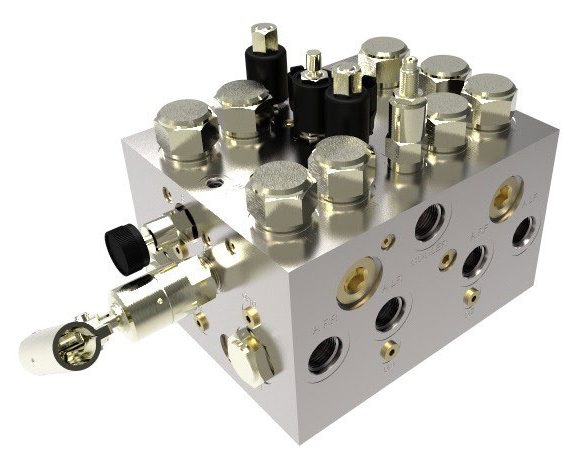
Design Steps
1. First, determine the relative position of the external oil port in the valve block based on the system layout and piping layout. Next, select the specifications of the joints according to the flow rate.
2. According to the working principle of the valve group, the system layout, the characteristics of the valve itself and the maintenance performance of the preliminary determination of the installation position of the control valve on the valve block;
3. Design and repeatedly optimize the flow paths between the external ports and the valve parts. Ensure that the flow paths achieve correct and reasonable communication according to the designed principle.
Design Points of Manifold Hydraulic
1. Design the manifold hydraulic with consideration for the direction of the system pipeline. Additionally, account for the space required for spanner operation. Moreover, for locations where similar ports might be easily connected incorrectly, design or choose pipe joints and hoses with different diameters. This will facilitate distinction and prevent incorrect connections.
2. Manifold hydraulic on the oil port should be marked next to the injection port marking (for example: P, A, T, B, A1, A2, B1, B2, M1, M2), of which, the plate valve mounting surface of the oil port marking is only reflected in the drawings, and used to connect with the rubber (steel) pipe external oil port and the pressure port next to the body of the valve must be playing the corresponding steel mark, in order to ensure that the installation of pipe joints (or flanges) after the marking does not cover the. To ensure that the mark remains visible after installing pipe joints (or flanges), position the steel mark more than 7mm from the edge of the corresponding oil port (as specified in the technical requirements).
3. Design the external oil port and pressure port on the valve block according to the connection size of the pipe joint. Leave suitable allowances for the outside diameter and depth of the countersunk hole and the depth of the thread to avoid interference during installation.
4. Choose the control valve structure form wisely and avoid excessive integration of the valve block. Specifically, avoid integrating too many threaded cartridge valves into the same valve block. Doing so will double the process holes and create a zigzagging oil circuit. Consequently, this increases pressure loss and complicates processing, inspection, and troubleshooting. On the other hand, for relevant functions, integrate parallel oil circuit plate valves as much as possible to simplify the system piping.
5. The mounting surface of the plate-type hydraulic control valve on the valve block should be designed according to the dimensions provided by the manufacturer’s samples, and the quality of its surface processing can be referred to the standard ‘ISO 4401 Hydraulic fluid power – Four-port directional control valves – Mounting surfaces’ or ‘GB/T 2514 Hydraulic transmission Four-port directional control valve mounting surfaces’. Surfaces’ or “GB/T 2514 Hydraulic transmission four-port directional control valves mounting surface” of the relevant provisions.
6. Design the threaded cartridge valve mounting holes on the valve block according to the dimensions provided in the manufacturer’s catalog. Furthermore, use these dimensions in conjunction with plug-ins that are compatible with other brands and models. Additionally, ensure that the plug-ins work with existing machining tools.
7. When designing the orifice of the valve block body, consider minimizing flow resistance loss and ensuring ease of processing. Generally, the recommended flow rate of the working pipeline is 8m/s, and the recommended flow rate of the return pipeline is 4m/s.
8. The hole depth value for the block is the depth calculated from the surface of the view in which the orifice is located and including the drill tip.
9. To facilitate deburring and avoid contaminant deposition, design intersecting holes in a T-shaped form. Specifically, ensure that the depth of one of the holes extends from the end face of the hole to the axis of the communicating aperture. In contrast, avoid using a cross-shaped design.
10. Avoid using inclined orifices. If you must use inclined orifices, ensure that the angle of inclination does not exceed 35°. Additionally, ensure that the orifices seal well.
11. In order to prevent the system from being punctured in use, the minimum wall thickness between two adjacent (intersecting or parallel) orifices in the middle of the valve block (including mounting threaded holes) shall be not less than 4 mm, except that, subject to layout and structural constraints, and when the orifices are subjected to a pressure of less than 6.3 MPa, the minimum wall thickness between the orifices may not be less than 3 mm.
12. Consider that the oil holes in the integrated manifold hydraulic system are thin and long, which may lead to misalignment during the drilling process. Therefore, increase the actual wall thickness appropriately based on the calculation to account for this issue.
13. To avoid damage to the drill bit, the depth of the hole should not normally exceed 25 times the diameter of the hole.
14. To facilitate the cleaning, washing, and inspection of the orifices, it is advisable to block process orifices using screw plugs, flanges, or other removable means. Moreover, in locations where space is restricted, it is important to use ball-up type plugs for blocking holes with a diameter not greater than 12mm. Additionally, ensure that the installation size of these ball-up type plugs complies with the provisions of “JB/T 9157-1999 Hydraulic and Pneumatic Use of Ball-Up Type Plug Installation Dimensions” to maintain proper functionality. Moreover, confirm that all specifications align with these requirements to ensure proper functionality and prevent any issues during operation.
15. We recommend that the block’s process orifice plugs do not protrude beyond the surface of the mounting surface.
16. The surface of the valve block is nickel-plated, the thickness of the nickel-plated layer is 0.008-0.015mm.
17. For complex valve blocks where a cutaway view cannot clearly show the intersection of internal bores, it is essential to indicate the intersection of the bores in a bore system table. This step will facilitate block inspection. Additionally, you should attach the working principle diagram of the valve block to the engineering drawings. Furthermore, make sure to include the three-dimensional axonometric drawing of the valve block.
Contact Zhuo Yi Control Technology for the latest production technology!


