1、Functional structure of the host
Fast forging hydraulic machine is an important forging production equipment, with a high degree of automation, high forging frequency, made of precision control of dimensional accuracy, etc., suitable for all kinds of metal materials forging processing, especially in the production of special steel and alloys, the poor plasticity of these materials, deformation resistance, narrow range of hot processing temperature, the requirements of the forging equipment, large capacity, fast speed.
According to the forging requirements, the hydraulic machine organic operation can be divided into ordinary forging and fast forging two kinds of working conditions: ordinary forging, the system pressure is 25MPa, the master cylinder output force of 20MN, the return force of 1MN, forging frequency of 35~45 times/min; fast forging, fast forging stroke of 30mm, the output force of 4MN. fast forging frequency of 85 times/min.
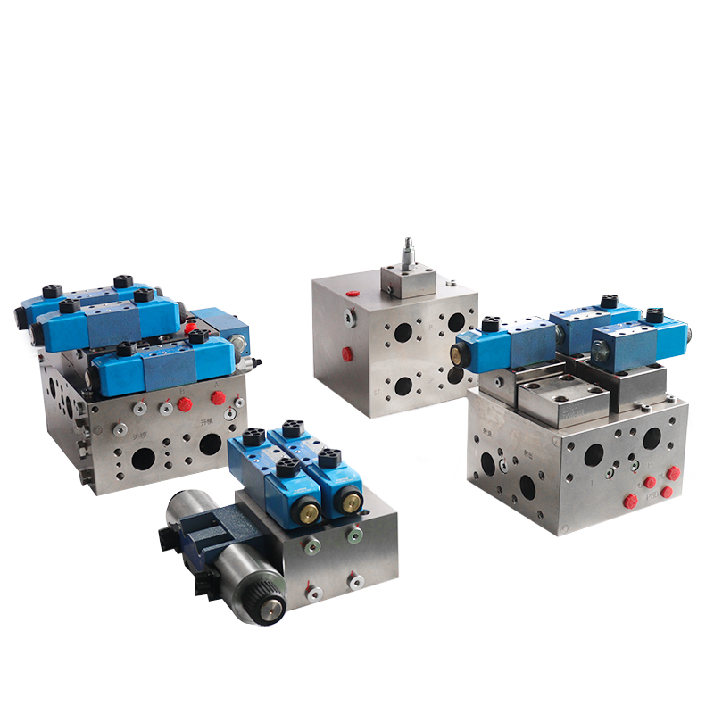
The machine hydraulic systems adopts electro-hydraulic proportional cartridge valve control. The hydraulic systems of the machine adopts electro-hydraulic cartridge valve control.

2、Hydraulic systems principle
(1) Role of components
The hydraulic systems principle of the hydraulic machine as shown in Figure 4-61, the system has 6 groups of quantitative pump (Figure 4-3 only draw a pump group) oil supply, each group flow rate of 540L/min, motor power of 250kW, through different groups of flow combinations, so that the hydraulic machine has a different working speed and forging times. The actuating elements of the system are plunger-type master cylinder 11 and single-acting piston type lifting cylinder 21, which are used to drive the slide down and up to complete the forging operation.
Plug-in 2 is a check valve, used to prevent backflow of pressure oil to protect the hydraulic pump; plug-in 3 and its pilot control valve (relief valve 4 and two-position four-way electromagnetic directional valve 5) constitutes an electromagnetic relief valve, used for hydraulic pump maximum pressure setting and unloading control.
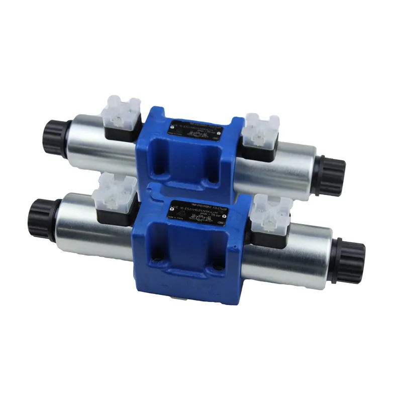
The two-position two-way electro-hydraulic proportional directional valve 6 is used for inlet oil on-off control when the master cylinder goes down, the plug-in 7 is used as the inlet oil circuit check valve of the plunger master cylinder 11, the plug-in 8 and its pilot valve (electro-hydraulic proportional relief valve 9) are used for the control of the forging pressure of the master cylinder down, the hydraulic check valve 10 is used for the self-gravitating charging of the plunger master cylinder 11 and the return of oil from the oil tank after the reversed opening, and the two-position four-way electro-hydraulic valve 22 is used for the reversed conduction of the valve. control.

The two-position two-way electro-hydraulic proportional directional valve 12 is used for the inlet oil on/off control when the hoisting cylinder is hoisted, the plug-in 15 is used as the check valve of the inlet oil circuit of the hoisting cylinder, and the plug-in 13 and its pilot valve (two-position two-way electro-hydraulic proportional directional valve 12) are used for the control of the upward pressure of the slide driven by the single-acting piston type hoisting cylinder 21.
Inserts 16, 17 and its pilot valve (two-position four-way solenoid directional valve 18) is used to control the slider downward when the lift cylinder rod chamber of the return line of the on-off control.
The system uses the two-position four-way electromagnetic directional valve 19 as the pilot valve to control the opening and closing of the plug-in 20. This action turns the rod chamber of the accumulator 23 and the lift-back cylinder on and off. Accumulator 23 serves two roles: first, it helps the main cylinder drive the slider down quickly during forging operations by squeezing the return cylinder oil; second, it supplies oil to the return cylinder to make the slider rise quickly after forging ends.
Hydraulic systems also has a self-circulating filter cooling system to ensure that the system works continuously when the hydraulic oil has enough cleanliness and normal working temperature.
(2) Working Principle
1)Ordinary forging:
When working, the system energizes the two-position four-way electromagnetic directional valve 5 to switch to the upper position, and the hydraulic pump group 1 starts lifting pressure from unloading. The system energizes the electro-hydraulic proportional relief valve 9 to establish the forging pressure.
Two two-way electro-hydraulic proportional directional valve 6 energised, hydraulic pump pressure oil through the main pipeline and plug-in 7 (as a check valve) into the piston master cylinder 11, two four-way electromagnetic directional valve 18 energised switching to the right position so that the plug-in 16, 17 open, lifting the cylinder rod-less chamber connected to the tank, the slider quickly down, at this time, the liquid-controlled check valve 10 to open to the master cylinder to replenish the liquid.
When the upper anvil touches the workpiece, it begins to pressurize the workpiece. Once the pressurizing shapes the workpiece, the system de-energizes the two-position four-way electromagnetic directional valve 5 and unloads the hydraulic pump group 1.
The two-position four-way electromagnetic directional valve 18 powers off and restores to the left position shown in the figure. At this point, plugs 16 and 17 close. Meanwhile, the system energizes the two-position four-way electromagnetic directional valve 19, which causes the plunger-type master cylinder 11 to unload. Once unloading completes, the system energizes the two-position four-way electromagnetic directional valve 5. Additionally, the system energizes the two-position two-way electro-hydraulic proportional directional valve 12. As a result, the hydraulic pump pressure oil enters the rod chamber of the lifting cylinder through plug 15. The slider rises rapidly until it reaches the set position, then stops, and the system enters the next cycle.
2) fast forging:
When the hydraulic pump group starts, the system establishes pressure. The two-position, four-way electromagnetic directional valve 19 energises, connecting the accumulator 23 with the single-acting piston type recovery cylinder 21. The electro-hydraulic proportional relief valve 14 energises, establishing the recovery pressure. At the same time, the electro-hydraulic proportional relief valve 9 energises, establishing the forging pressure.
The pressure oil from the hydraulic pump enters the plunger-type master cylinder 11 through the main pipe and insert 7. The ram then descends rapidly for forging, squeezing the oil from the lift-back cylinder into the accumulator. When the pressure reaches the point where the workpiece is shaped, the system de-energizes the two-position, four-way electromagnetic directional valve 5. As a result, the hydraulic pump unloads.
When the system de-energizes the electro-hydraulic proportional relief valve 9, it causes the plunger-type master cylinder 11 to open and relieve pressure. As the master cylinder pressure decreases, the oil pressure in the accumulator promotes the rapid return of the cylinder. Once the cylinder rises to the set position, it proceeds to the next forging.
3、Hydraulic systems characteristics
①
The hydraulic systems press system adopts a multi-pump oil source. It uses various flow combinations to meet the requirements for different working speeds and forging times. This approach is conducive to energy saving.
②
The system adopts a proportional valve and cartridge valve for control. This approach reduces the number of components and simplifies the structure of the oil circuit. It also facilitates the integration of electromechanics and liquids, which enhances the digital control of the system. As a result, the system improves forging accuracy and automation.
Additionally, the system offers high working pressure, large through-flow capability, and good sealing performance. It features fast response, strong anti-pollution ability, and safe, reliable action.
③
To achieve the system’s overload protection, set up the pressure sensor, unloading relief valve, and safety valve. Additionally, equip the hydraulic cylinder stroke with a travel switch. This switch reverses the oil circuit pressure relief and serves as the signal source to stop the hydraulic cylinder’s action. These measures improve the safety performance of the equipment.
④
The electro-hydraulic proportional relief valve 14, plug-in 20, and accumulator 23 together form a hydraulic spring. This setup absorbs pressure energy as the system forges the slider downward. The system then releases this hydraulic energy as it raises the slider back up. This process improves the running speed and enhances system stability.
Contact Zhuo Yi Control Technology for the latest production technology!